Top Flite TOPA0160 User Manual
Page 29
❏ ❏
8. Use the remainder of the 3/32” x 6” x 30” [2.4 x
152.4 x 762mm] balsa sheet you used for the forward
inner top skin to make a forward inner bottom skin.
Test fit, then glue the skin to the wing panel.
❏ ❏
9. After the glue dries remove any T-pins you
may have used and take the weights off the wing
panel. Trim all the sheeting so it is even with the tip
and root ribs and the leading and trailing edges of
the wing.
Perform the following step only if you are installing
fixed landing gear.
❏ ❏
F10. If you are installing fixed landing gear, use
the plan as a guide to poke holes through the wing
skin with a pin until you locate the groove in the
landing gear rail. Remove a strip of balsa from the
groove just long enough to accept the landing gear
wire. Use the nylon straps as a template to mark
holes in the sheeting for the #2 x 3/8” [9.6mm]
screws. Drill 1/16” [1.6mm] holes at the marks and
test fit the landing gear to the wing with the straps
and screws as shown on the plan. Remove the
landing gear.
Note: The nylon straps should be inset into the balsa
skin so that they are secured to the basswood
landing rail.
❏
11. Set the right wing panel aside and sheet the
bottom of the left wing panel the same way.
BUILD THE WING TIPS
Refer to this photo for the following steps.
❏
1. Locate the 1-1/2” x 1-9/16” x 9” [38 x 39.7 x
228.6mm] shaped balsa wing tips. Check the shape
of the tips against the plan and sand as needed to fit.
❏ ❏
2. Glue the wing tip to the wing. Keep the tip
centered on the wing.
❏ ❏
3. Use a razor plane or a hobby carving knife,
followed by sanding to carefully shape the wing tip.
Inspect your progress frequently. Use the plan and
the above photo as a reference so you know what
the curve of the tip should look like.
Note: When you shape the second wing tip, use the
finished tip as a guide to shape the second. This way
you can make sure both of the wing tips are identical.
❏
4. Return to step 2 and build the wing tip on the
left wing panel.
❏ ❏
R4. Brush another coat of fuelproof paint
inside the wheel wells while they are still easy to
reach with a paint brush.
❏ ❏
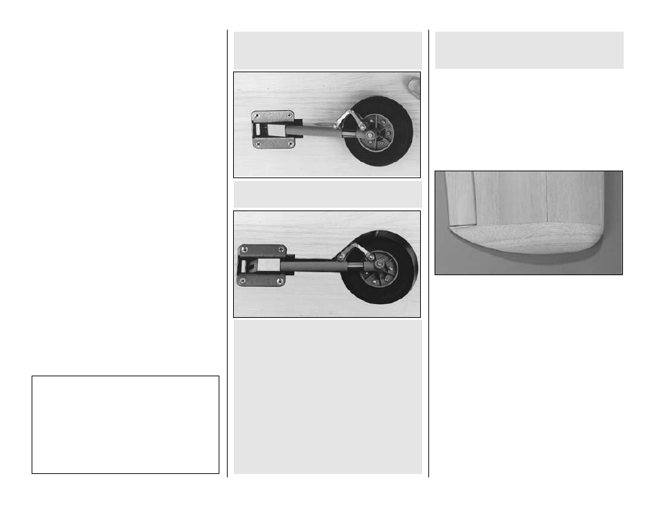
R2. Retract the gear so that the wheel lays on
the wing sheeting and draw a rough outline of the
wheel onto the sheeting. Cut the sheeting within the
outline. Retract the wheel again and draw a more
accurate outline. Cut the sheeting until the wheel
fully retracts into the wheel well, leaving at least 1/8”
[3.2mm] clearance between the wheel and the
sheeting (in case you
tweak your landing gear on
one of those bumpy landings).
❏ ❏
R3. Glue leftover 1/16” [1.6mm] balsa sheeting
to the inside of the bottom sheeting around the
wheel well cutout with the grain direction opposite
that of the wing sheeting. This will reinforce the
sheeting around the wheel well cutout.
❏ ❏
R1. Start by cutting and removing just enough
sheeting to mount the landing gear to the rails.
CUT OUT THE WHEEL WELLS
Perform these steps only if you are installing retracts.
T-34 Fact: The production T-34A was powered by
a 225 hp Continental O-470-13 engine. The
aircraft was fitted with either an eighty-four or
eighty-eight inch diameter, hydraulically operated
propeller. The aircraft had tricycle retractable
landing gear that was electrically operated. There
were two main landing gear doors. The inner main
gear door opened during gear transition and then
closed when the gear was up or down.
-29-