Build the fuselage – Top Flite TOPA0160 User Manual
Page 34
and a solder clevis. We recommend silver solder for
the solder clevis (see the hot tip on soldering below).
Drill 1/16” [1.6mm] holes in the aileron horn mounting
plate for the control horn (see previous sketch for
correct alignment). Be sure to align the horn with the
servo arm. Add a few drops of thin CA to the holes and
allow to harden. Mount a control horn to the aileron
with two #2 x 3/8” [9.5mm] screws and hook up the
servo with the pushrod.
❏ ❏
3. Thread another nylon clevis onto the end of
another .074” x 4” [1.9 x 101.6mm] threaded end
wire. Bend and cut the wire to the length shown on
the wing plan for the right flap pushrod. Enlarge the
holes in your flap servo horns with a hobby knife (or
a #48 drill for perfection) and connect the flap
pushrod to the servo horn using a nylon FasLink™.
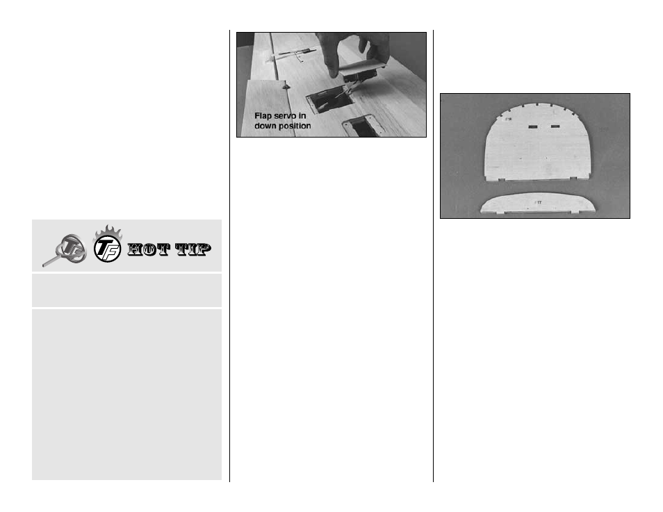
Rotate the flap servo arm to the
down position and
set the flap hatch cover (with the flap servo and
pushrod connected) over the flap hatch and guide
the pushrod out of the hole in the TE.
❏ ❏
4. Temporarily connect the clevis to the flap horn
to see if the pushrod is approximately the correct
length.
❏
5. Connect the other aileron and flap pushrod the
same way. Make final adjustments to the lengths of
the pushrods when you set up your radio.
This is as far as we can go with the wing until it is
fitted to the fuse. But first, we need a fuse, so...let’s
build the fuse!
BUILD THE FUSELAGE
PREPARATION
Note: The die-cut 1/8” [3.2mm] plywood formers are
stamped with only the necessary portion of their
name. For example, F-2B is stamped 2B. All die-cut
parts are 1/8” [3.2mm] plywood unless they are
otherwise noted.
❏
1. Position the bottom view of the fuselage plan
over your flat building board. Cover it with Plan
Protector or waxed paper. You may cut the bottom
view from the rest of the plan.
Note: This is a
bottom view of the fuselage.
❏
2. Use 30-minute epoxy to glue two die-cut 1/8”
[3.2mm] plywood F1B’s together and F1T to the front of
F1DT (there are two F1DT’s included in the kit but only
one is used). Make sure the punch marks are visible on
F1T. Clamp the assemblies to a flat table or board or lay
weights on them with waxed paper underneath. Inspect
the parts closely before the epoxy cures to make sure
they remain aligned. Wipe away excess epoxy before it
cures. From now on the F1B assembly will be referred
to as the
firewall.
❏
3. Drill 1/16” [1.6mm] holes through the punch
marks in F2D and F2 that are closest to the bottom
of the formers. Glue F2D to the front of F2 with the
holes aligned. After the glue dries, drill 5/16” [7.9mm]
holes through the punch marks. If you do not have a
5/16” [7.9mm] drill bit you can start with a 1/4”
[6.4mm] hole and enlarge it to approximately 5/16”
[7.9mm] with a hobby knife or a round wood file.
These holes do not have to be
exactly 5/16” [7.9mm]
or perfectly round.
❏
4. If you’re installing retracts, drill 1/8” [3.2mm] holes
through the punch marks in the bottom of F6 for the air
tank dowels and through the punch marks in F2 for the
pull/pull nose steering cable guide tubes.
A. Thoroughly clean the parts to be soldered with
alcohol or other solvent.
B. Roughen the areas to be soldered with fine
sandpaper. Clean again.
C. Apply soldering flux or soldering acid to both parts.
D.
Tin
the joining areas of both parts (heat the part and
coat it with a thin coat of solder). Apply more
soldering flux.
E. Join the parts as you apply heat. Apply more solder
and make sure it flows into the joint.
F. Do not move the parts until the solder has solidified.
G. Test the joint by pulling hard.
H. Remove excess flux with alcohol or other solvent.
Inspect the joint. A secure solder joint has a shiny
appearance. If the solder is rough appearing or not
shiny, reheat and allow to cool.
I. Coat the parts with a thin film of oil.
SILVER SOLDERING
Use this process when soldering.
-34-