Top Flite TOPA0160 User Manual
Page 35
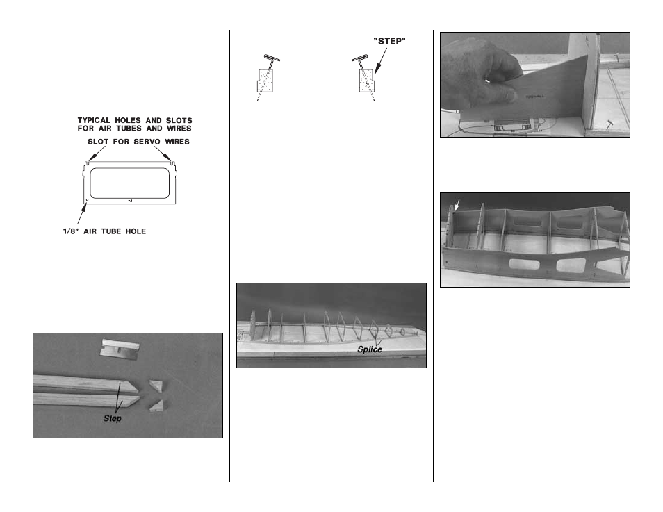
❏
5. Drill 3/16” [4.8mm] holes through the punch
marks in the die-cut 1/8” [3.2mm] plywood formers
F6 through F10. When you drill the holes, press
down on each former to prevent the wood from
splitting when the drill bit goes through. Also drill
3/16” [4.8mm] holes for the antenna tube in formers
F7 through F11.
❏
6. If you plan to install the Top Flite Beechcraft
T34B Scale Cockpit Kit (TOPQ8413), drill holes and
cut slots in the formers for routing the air lines and
servo wires between the fuse sides and the cockpit
interior in formers F3, F4 and F5.
BUILD THE BOTTOM OF THE FUSELAGE
❏
1. Cut a 45 degree angle at the aft end of two 1/4”
x 3/8” x 36” [6.4 x 9.6 x 914mm] stepped balsa side
stringers so you can
splice them onto another
stringer later.
❏
2. Pin the stringers over their location on the plan
so the
step is on the bottom and faces the outside of
the fuselage. The front end of the stringers should
align with the dashed lines near the front and
extend past the firewall by 1/8” [3.2mm]. Use plenty
of T-pins to hold the stringers down so they conform
to the curvature of the plan.
❏
3. Cut another 1/4” x 3/8” x 36” [6.4 x 9.6 x 914mm]
stepped balsa side stringer in half. Bevel one end of
both stringers to match the angles you cut on the
stringers already pinned to the plan. Pin these
stringers to the plan and glue them to the front stringers
with thin CA. Trim the ends so they extend past former
F11 by approximately 1/8” [3.2mm]. You can see the
splice in the following photo.
❏
4. Position but do not glue formers F1 through F11
on the side stringers so the embossed names on the
formers face forward. Adjust the stringers as needed.
Are your 3/16” [4.8mm] pushrod holes drilled?
❏
5. Glue formers F2 through F11 to the side
stringers, holding them vertical with a 90 degree
triangle. Don’t be concerned about formers that are
slightly warped or twisted–that is normal. You will be
able to straighten these formers when you glue the
3/16” [4.8mm] stringers to them.
❏
6. Glue the firewall to the side stringers using the
die-cut 1/8” [3.2mm] plywood firewall angle gauge
to hold the firewall at the correct angle. This will
establish the correct down thrust for the engine.
❏
7. Test fit, then glue the die-cut 1/8” [3.2mm]
plywood fuse side doublers to formers F2 through
F6 only and to the side stringers. Do not glue the
doublers to the firewall until the next step. You may
have to reposition some of your T-pins so they do not
interfere with the side doublers. Use your 90 degree
triangle to hold the formers vertical while you glue
the doublers to them.
❏
8. Glue the fuse side doublers to the firewall with
30-minute epoxy using the firewall angle gauge to
make sure the firewall is set at the correct angle. Use
a large C-clamp or masking tape to securely hold the
doublers to the firewall until the epoxy fully cures. Cut
one 3” [76.2mm] long piece from each of the (2) 1/2”
x 36” [12.7 x 914mm] balsa tri-stock pieces. Shape
the pieces so they fit between the firewall and the
fuse sides on both the left and right sides behind the
firewall. Glue them in place with 30-minute epoxy.
-35-