Top Flite TOPA0160 User Manual
Page 24
❏ ❏
17. Optional: From the plan cut off the two
paper tube strips along the dashed lines. Roll these
strips and cut them to the lengths needed. They are
used to allow easy routing of the servo wires and
their extensions. For fixed gear the tubes go from R2
to R9. For retracts they go from R7 to R9. For retract
installation, the wires can easily be fished through
the small holes in R4, R5 and R6.
❏ ❏
18. Cut three 3-1/16” [77.8mm] long servo
hatch cover rails from the 1/4” x 3/8” x 24” [ 6.4 x
9.6 x 610mm] basswood stick (the same stick you
used for the landing gear rail support if you are
building retracts). Glue the rails in the notches of the
ribs where shown on the plan.
❏ ❏
19. Cut three 1-1/2” [38mm] long flap hinge
blocks from the shaped 5/8” x 9” [15.9 x 229mm]
balsa stock. Bevel one end of each hinge block so
they fit the ribs, then glue them in the location shown
on the plan. See the cross section on the wing plan
to be sure you know the position and orientation of
the blocks.
❏ ❏
20. Cut five 1” [25.4mm] long aileron hinge
blocks from a 1/2” x 1/2” x 6” [12.7 x 12.7 x 152mm]
balsa stick. Cut one 2-7/8” [73mm] long hinge block
from the 5/8” x 1/2” x 6” [15.9 x 12.7 x 152mm] balsa
stick. The long hinge block is the one closest to the
root end of the aileron and is the base for the aileron
control horn.
❏ ❏
21. Bevel the ends of all the aileron hinge
blocks so they fit against the ribs as shown on the
plan. Bevel the tops of the hinge blocks that fit in the
aileron so they match the angle of the ribs. Glue the
hinge blocks in the wing and aileron.
❏ ❏
22. Use a bar sander and 80-grit sandpaper to
sand the sheeting, spars and LE so they are flush
with root rib W2 and tip rib W14.
❏ ❏
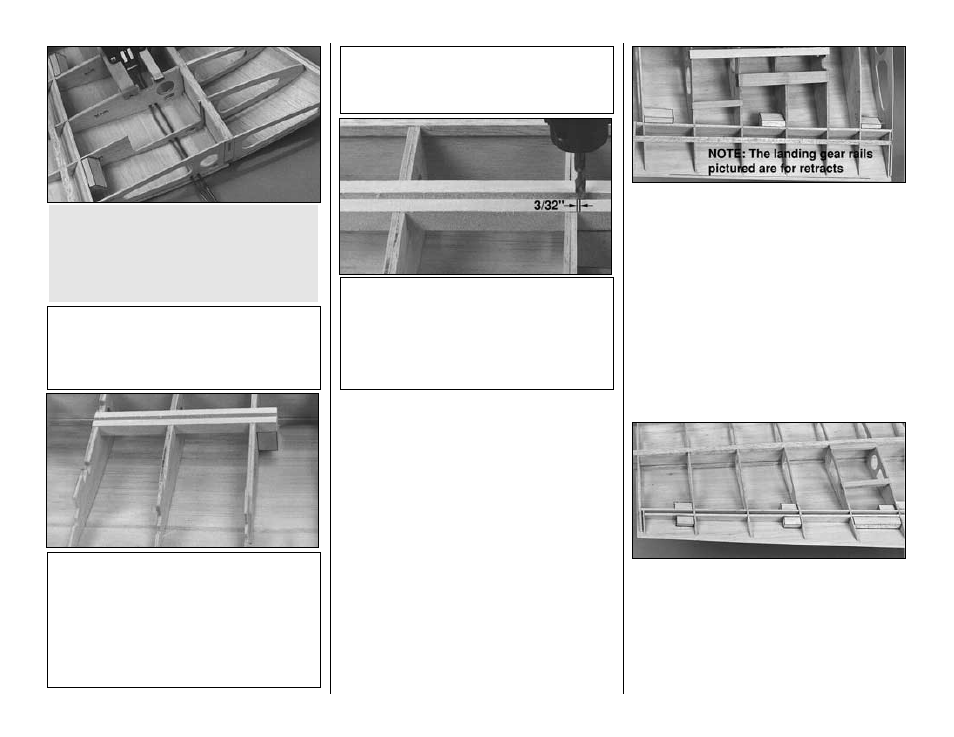
F16. After the epoxy on the landing gear rail
has fully cured, drill a 3/16” [4.8mm] hole through
the landing gear rail and the torque block. The
center of the hole should be 3/32” [2.4mm] from
the plywood rib doubler W4G. Make sure you hold
the drill perpendicular to the bottom of the landing
gear rail.
❏ ❏
F15. Cut the 1/4” x 1/2” x 9” [6.4 x 12.7 x
229mm] plywood flap servo hatch forward rail
to a length of 3-1/16” [77.8mm]. Glue it into the
notches of ribs W6 and W7.
❏ ❏
F14. Use 30-minute epoxy to glue the 1/2” x
3/4” x 6-3/4” [12.7 x 19 x 172mm] grooved
hardwood landing gear rail in the notches of the
ribs and rib doublers with the groove visible, as
shown in the photo. At the same time, glue the
3/4” x 3/4” x 1” [19 x 19 x 25.4mm] maple torque
block to rib doubler W4G and the top of the
landing gear rail.
Perform steps F14-F16 if you are installing fixed
landing gear.
NOTE: The fixed landing gear rail and rib
doublers are shown on the left wing plan.
❏ ❏
R13. Now is a convenient time to plan your
air line routing. If you haven’t already done so,
drill or cut holes in the ribs to guide the air lines.
A 5/32” [4mm] brass tube sharpened at one end
makes a great
drill to cut holes through the ribs.
Do not install the air lines at this time.
-24-