Top Flite TOPA0415 User Manual
Page 58
wood blade from a block of basswood and using it as a
mold to vacuum-form four front halves and four back
halves from .030" ABS plastic sheet. The halves were
glued together making four complete blades. We glued
a 1/2" x 6" wood dowel into the root of each blade so
they could be plugged into the hub.The hub was shaped
from a basswood block with a rotary tool and a drill
press. The spinner was turned on a lathe from a
basswood block, then joined to the hub. The bolts were
added later. Finish your display prop with a Hamilton
Standard decal sheet by Major Decals (MAJQ0006),
followed by a light coat of flat clear LustreKote.
The Curtiss electric prop (13ft. dia.) would be easier to
model due to the simplicity of the hub and the closer
resemblance to model airplane propellers–you could
purchase two oversize wood model airplane props,
round the tips and join them in a four-blade fashion. A
spinner could be made from a wood dowel.
GET YOUR MODEL READY TO FLY
Balance your model
NOTE: This section is VERY important and must
NOT be omitted! A model that is not properly
balanced will be unstable and possibly unflyable.
At this stage your model should be in ready-to-fly
condition with all of the systems in place including
the engine, landing gear, scale details, covering and
painting and the radio system (less the receiver and
battery pack). After you find out where the C.G. is
right now, you can mount the receiver and battery
pack in a location that will minimize (or eliminate) the
amount of additional ballast required to get the C.G.
at the correct location.
❏
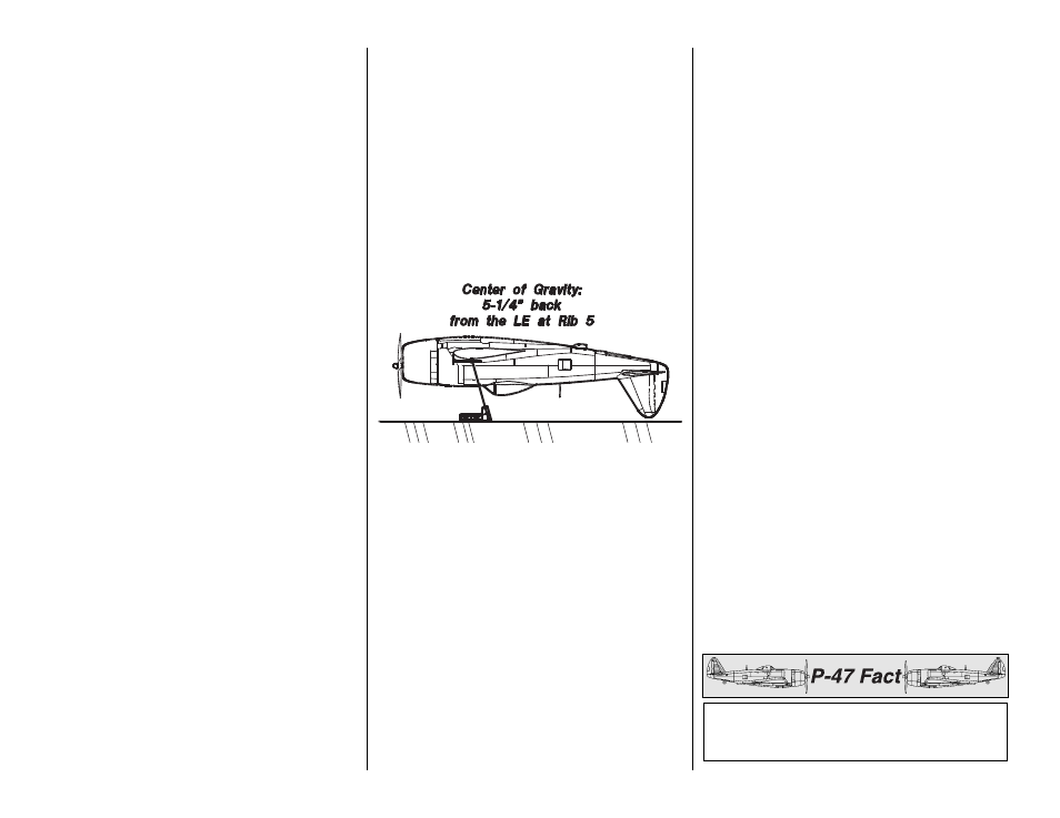
1. Accurately mark the C.G. on the top of the wing
on both sides of the fuselage. The C.G. is shown on
the plan (CG) and is located 5-1/4" back from the
leading edge at the location of rib 5 (not alongside
the fuse). This is where your model should balance
for your first flights. Later, you may wish to
experiment by shifting the C.G. up to 1/2" forward or
back to change the flying characteristics. Moving the
C.G. forward may improve the smoothness and
arrow-like tracking, but it may then require more
speed for takeoff and make it more difficult to slow
down for landing. Moving the C.G. aft makes the
model more agile with a lighter and snappier feel. In
any case, start at the location we recommend and do
not at any time balance your model outside the
recommended range.
❏
2. With the wing attached to the fuselage, all parts of
the model installed (ready to fly), an empty fuel tank
and the landing gear retracted (up), place the model on
a Great Planes C.G. Machine at the balance point you
marked, or hold it upside-down with the stabilizer level.
Note: It will be necessary to substitute the base rods
that come with the C.G. Machine with longer base rods.
❏
3. If the tail drops, the model is “tail heavy" and
you must add weight* to the nose to balance. If the
nose drops, it is “nose heavy” and you must add
weight* to the tail to balance.
*If possible, first attempt to balance the model by
positioning the battery pack and receiver where
required. If you are unable to obtain proper balance
by doing so, then it will be necessary to add weight to
the nose or tail to achieve the correct balance point.
NOTE: Nose weight may be easily installed by gluing
lead weights into the engine compartment. Do not
attach weight to the cowl. It is not intended to support
weight. Tail weight may be added by using Great
Planes (GPMQ4485) “stick-on” lead weights and later,
if the balance proves to be OK, you can open the fuse
bottom and glue these permanently in position.
❏
4. Once you have determined where to mount the
battery pack and receiver and any additional weight
required to achieve the correct balance, take the
model off the balance stand and remove the wing.
❏
5. Mount the receiver and battery pack. As you
can see in previous photos we mounted our receiver
on a plate (with R/C foam rubber in between) made
from leftover 1/8" plywood that was attached to the
servo tray. The battery pack was wrapped in R/C
foam rubber and securely held in position above the
fuel tank with a sheet of lite-ply. Simply stuffing the
battery pack into position with foam rubber is not
sufficient. Attach additional lead weight to the tail or
nose as necessary.
❏
6. Mount the receiver on/off switch and charging
jack where they can be connected to the receiver
and battery pack and will be readily accessible from
outside the model. Secure the connection between
the battery pack and the switch with vinyl tape, heat
shrink tubing or special clips suitable for that
purpose. Route your receiver antenna inside or
outside the fuselage.
❏
7. Mount the wing onto the fuse and recheck the
C.G.
The cost of production P-47’s as delivered was
$82,997 for a B model in 1942, $79,752 for a D
model in 1944 and $78,642 for an N model in 1945.
-58-