Top Flite TOPA0415 User Manual
Page 22
❏
6. Test fit, then glue both die-cut 1/8" plywood tail
gear braces to formers 7 & 8 and the main stringer
as shown.
Refer to this photo for the following seven steps.
❏
7. Use coarse sandpaper to scuff three 3/16" x 48"
pushrod guide tubes and two 3/16" x 36" pushrod
guide tubes so glue will adhere. The longer tubes are
for the elevator and rudder and the shorter tubes are
for the tail gear pull-pull steering cable.
❏
8. Use the precut notches in the ply stab saddles
as a guide to cut the pushrod exit slots in the
sheeting on both sides of the fuse.
❏
9. Slide the 48" long guide tubes through the holes in
the formers and out the exit slots you just cut in the
back of the fuse. Note that there are two tubes on the
left side of the fuse (for the elevator and rudder) and
one tube on the right side of the fuse (for the elevator
only). Slide the 36" long tubes through the holes in
the formers for the tail wheel steering cables. Do not
glue the guide tubes in place until instructed to do so.
❏
10. Glue eight 1/4" x 1/4" x 30" balsa sticks into
the notches of formers 4 through 9 for the bottom
stringers. The stringers nearest the main stringer on
both sides of the fuselage aren’t long enough, so
they’ll have to be spliced together from two stringers.
As you proceed, straighten any twists in the formers
by holding them in position while you glue the
stringers into the notches.
❏
11. Glue the pushrod guide tubes into the exit
slots in the back of the fuse with 30-minute epoxy
mixed with microballoons. Glue the guide tubes to
the formers with CA.
❏
12. After the epoxy has fully hardened, sand the
pushrod guide tubes flush with the fuse sides.
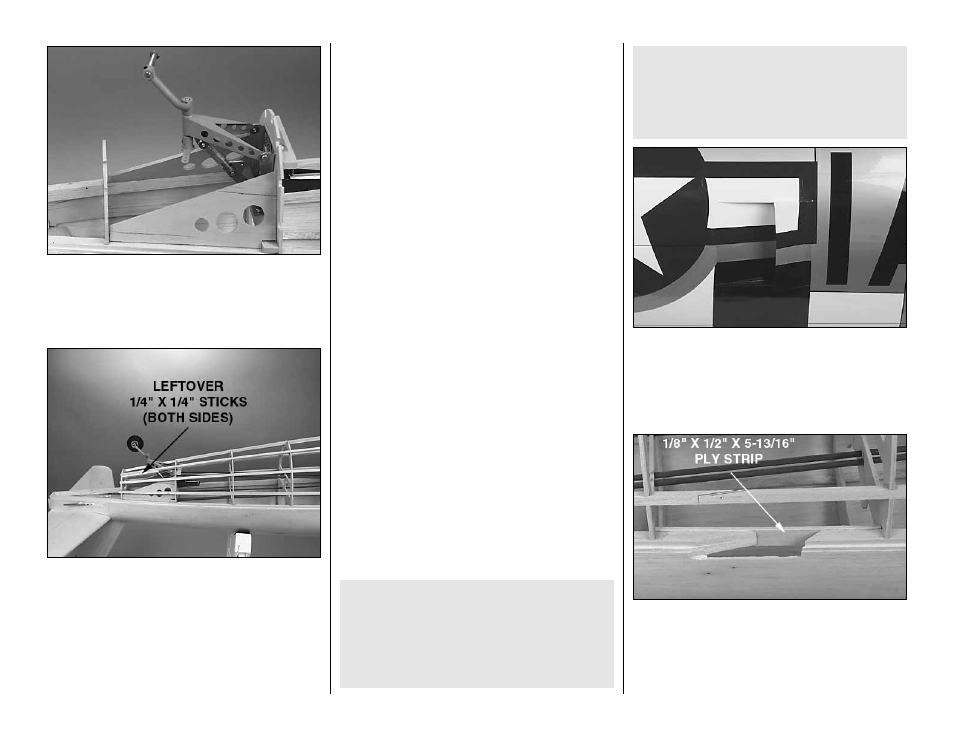
❏
13. Glue a leftover 1/4" x 1/4" stick to former 9 and
the stringers as shown. This will help support the
sheeting when the opening for the tail wheel is cut.
❏
14. Mount a 1-3/4" tail wheel to the tail gear axle.
If necessary, enlarge the hole in the tail wheel with a
#9 drill (a 13/64" drill would work okay). Use a cutoff
wheel to cut the axle to the correct length. File a flat
spot on the axle for the set screw, then temporarily
mount the tail wheel to the tail gear.
Perform steps 15 and 16 only if the intercooler
doors will be open.
❏
15. Cut two 1/2" x 5-13/16" strips from leftover
1/8" plywood.
❏
16. Cut out the main stringers as shown on the
plan and in the photo. Glue the strips of plywood
across the inside of the main stringers.
That’s all we need to do on the intercooler doors for
now. The rest will be done after the fuse is sheeted.
through the main side stringers to accommodate
the inner doors, construct the doors, then paint
them to match the trim scheme. Often, the stars
and bars on the fuse sides cross over the doors,
making for an intricate and time-consuming paint
job (see the photos on the kit box).
Before you continue, decide whether you will
feature the intercooler doors on the fuselage
sides open or closed. If you decide to show the
doors closed, skip the next two steps. All you’ll
need to do is add panel lines depicting the doors
after the model is finished. If you wish to feature
the intercooler doors open, you will have to cut
-22-