Top Flite TOPA0415 User Manual
Page 50
❏
9. Once you have positioned the cowl mounts and
the cowl rings, remove one of the cowl ring sections,
add medium CA, then carefully reposition the cowl
ring, permanently gluing it into position. Glue the
remaining five cowl ring sections into position the
same way. Do not glue the cowl mounts to the
fuselage until after the fuse is covered.
❏
10. Remove the cowl mounts. Sand the cowl ring
sections even with the fuselage. Round the edges as
shown on the plan. As you can see, this is easily
done with the cowl mounts off the model.
❏
11. Reposition the cowl mounts to the fuse. Drill
1/16" holes through the elongated holes in the cowl
mount bases and into former 1. Temporarily hold the
cowl mounts in position with six #2 x 3/8" screws and
#2 washers. The cowl mounts will be permanently
glued in place after the model is covered.
❏
12. Cut six 1" x 1" squares from the leftover 1/32"
ply sheeting (from the flap area of the wing). Glue the
squares to the inside of the cowl where they will align
with the cowl mounts.
❏
13. Mount the engine to the fuse. Place the cowl on
the fuse and mount a prop on your engine. Align the
cowl so the prop will have clearance all the way
around and is centered on the engine. View the
alignment of the cowl with the engine and the fuselage
from all angles. Make adjustments as needed.
❏
14. Have an assistant hold the cowl in position, or
use masking tape. Drill 3/32" holes through the cowl
and the cowl mount blocks. Remove the cowl and
enlarge the holes in the cowl only with a 5/32" drill.
Add a few drops of thin CA to all the holes and allow
it to harden.
❏
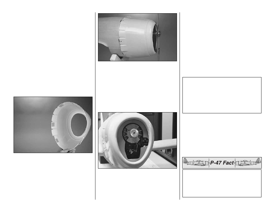
15. Test mount the cowl to the cowl mounts with
six #6 x 1/2" screws and #6 washers.
Refer to this photo while building the engine
baffle in the next few steps.
❏
16. Now that you’ve mounted the cowl, use the
template on the plan to make an engine baffle from
1/8" lite plywood (not included). The baffle will guide all
incoming air over the head and cylinder of the engine
for maximum cooling. The cutout is for the US Engine
41cc. If you are using a different engine, you’ll have to
make the cutout by trial and error fitting.
❏
17. Test fit, then temporarily tack-glue the baffle
into the cowl against the lip that joins the cowl front
to the sides. Trim as necessary for a good fit.
❏
18. Fit the cowl to the engine, trimming the
opening in the baffle as necessary until you have
achieved adequate clearance all the way around.
❏
19. Remove the cowl. Determine the location of
accessories to be mounted inside the cowl, such as an
ignition switch (if using an ignition engine), fueling
system, remote glow igniter, air fill valve, etc.Temporarily
mount those items where you prefer, then cut holes in
the cowl to access them. Cut additional holes where
necessary for the exhaust outlet and the needle valve.
❏
20. Glue the baffle to the cowl. Reinforce the seam
between the cowl front and sides with several 3-inch long
strips of 1" glass cloth and 30-minute epoxy. Reinforce the
seams on the top and bottom of the cowl sides and around
the cowl flaps with additional strips of 1" glass cloth and
epoxy. While you’re at it, use some of the leftover epoxy to
lightly coat the plywood baffle so it will be fuelproof and water
resistant when wet-sanding the cowl.
With demand for P-47’s beginning to exceed
production capabilities at the Evansville and
Farmingdale plants, a third factory was needed.
Under license, the Curtiss Aircraft Company in
Buffalo, NY, began production on the P-47G,
identical to P-47D’s.
Note: IMAA rules specify that magneto spark
ignition engines must be equipped with a manually
operated coil-grounding switch to stop the engine.
This switch must be mounted in a location that is
readily available to both the pilot and the helper. As
mentioned in the front of the manual, Great Planes
makes an Ignition Switch Harness (GPMG2150)
that is suitable for this purpose.
-50-