Top Flite TOPA0415 User Manual
Page 28
❏
7. Mount the elevator control horn to the elevator
with four #4 x 3/8" screws. Mount the other control
horn and pushrod to the other elevator the same way.
❏
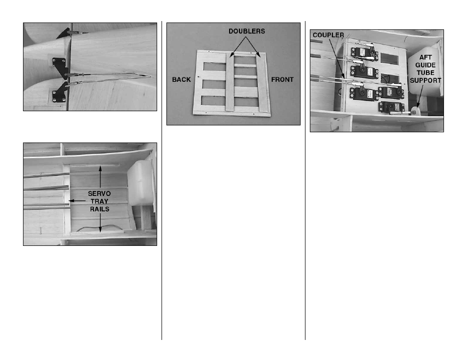
8. Cut the servo tray mounting rails from the
remainder of the 1/4" x 1/2" basswood stick you used
for the tail gear mounting rails. Use epoxy to glue the
aft rail to former 4 in the notches of the crutches and
glue the side rails to the crutches. Note that the
wide
side of the side rails is glued to the crutch.
❏
9. Test fit the rudder and elevator servos in the
die-cut 1/8" plywood servo tray. The servo tray is
designed to accommodate most standard size
servos. If your servos do not fit, modify the tray as
necessary, or make another tray from 1/8" plywood
(not supplied).
❏
10. Glue both die-cut 1/8" plywood servo tray
doublers between the front servo cutouts across the
top of the servo tray
(remember, the servos are
mounted to the bottom of the tray).
❏
11. Position the servo tray in the fuse, then drill six
1/16" holes through the tray (two through both sides
and two more through the aft edge) and the servo
tray mounting rails. Remove the servo tray. Add a
drop of thin CA to the holes in the rails. Enlarge the
holes in the servo tray only with a 3/32" drill bit,
then test mount the tray to the rails with six #2 x 1/2"
screws and #2 washers.
Let’s hook up the throttle first. A 3/16" x 11-3/4"
pushrod guide tube and flexible plastic pushrod are
supplied in this kit for the throttle. This is the
recommended setup for ignition engines as metal
pushrods should not be used due to the possibility of
RF (radio frequency) noise. If you are using a glow
engine, you may substitute a metal pushrod or cable
(not supplied) if you prefer.
Refer to this photo to hook up the servos.
❏
12. Mark the firewall (or the isolation mount if you
are using one) where the throttle pushrod will align
with the arm on your carburetor. Drill a 3/16" hole
through the firewall and the iso plate at the mark you
made. If you are using the iso plate, enlarge the hole
in the plate with a 1/4" drill bit.
❏
13. Mount your throttle servo to the servo tray
using the screws that came with your radio. Hook up
the throttle using the 3/16" x 11-3/4" outer pushrod
guide tube, the 11-3/4" flexible plastic pushrod, a ball
link and a nylon clevis as shown on the plan. Glue
the outer guide tube to the firewall. Make an aft
guide tube support from leftover plywood and glue
it in position so the throttle pushrod aligns with the
throttle servo.
❏
14. Mount the two elevator servos in the servo
tray. Cut the pushrods to the correct length, then
silver solder them to the clevises and connect them
to the servos. Hint: Wipe away residual soldering
flux immediately after the solder has solidified. After
the joint cools, coat the clevis and the solder joint
with oil to prevent rusting. Note: If you would rather
connect the pushrods after the model is covered (so
they won’t be sticking out of the rear end of the
fuselage when you are covering), skip this step for
now and return after covering.
-28-