Isobus job computer : ic18 sprayer, Master screen – TeeJet IC18 SPRAYER JOB COMPUTER User Manual
Page 33
28
www.teejet.com
OVER
VIE
W
SE
TUP
APPENDIX
GE
TTING ST
AR
TED
OPER
ATION
ISOBUS Job Computer : IC18 Sprayer
Section or Icon
Description
Flow Based or Pressure Based
Icons
These symbols will only appear if both a flow sensor and a pressure sensor are installed.
Flow Based - displayed if a regulation is based on flow
Pressure Based - displayed if regulation is based on pressure.
Density
D
Displays a “D” to the left of the tank icon if the density is set to “Fertilizer” instead of water.
Boom Sections
Displays the active
and inactive
boom sections as well as if they are on
(spray is blue) or off
(spray is gray).
NOTE: The color on the boom sections indicates
the color of the selected nozzle type.
Circulation
SC
CC
If Circulation is installed and selected in the OEM Menu, “SC” (Semi Circulation) or “CC” (Full
Circulation) will be displayed.
NH3 Mode Active
NH3
Displays if the unit is in NH3 mode.
Sprayer ID Number
Displays the soft key number assigned to the displayed IC18 ECU.
Nozzle Information
This information section displays the nozzle type, recommended
pressure range, current working pressure and high pressure limit.
2 8
b a r
Nozzle Type
Displays the selected nozzle type
Recommended Pressure
Range
Displays the recommended pressure range for the selected nozzle (the
green area indicates the pressure range). The pressure range will change
depending upon the selected nozzle, working speed, etc.
IMPORTANT! ALWAYS REFER TO THE RECOMMENDED PRESSURE RANGE AS FAILURE
TO DO SO MAY RESULT IN UNEVEN SPRAY PATTERNS.
Current Working Pressure
Displays the current working pressure
NOTE: This pressure range should not exceed
the recommended pressure range.
IMPORTANT! ALWAYS REFER TO THE RECOMMENDED NOZZLE PRESSURE VALUES
WHEN SETTING NOZZLE PRESSURE.
Current Pressure Rate
Displays the current pressure to the nozzle
2 8
b a r
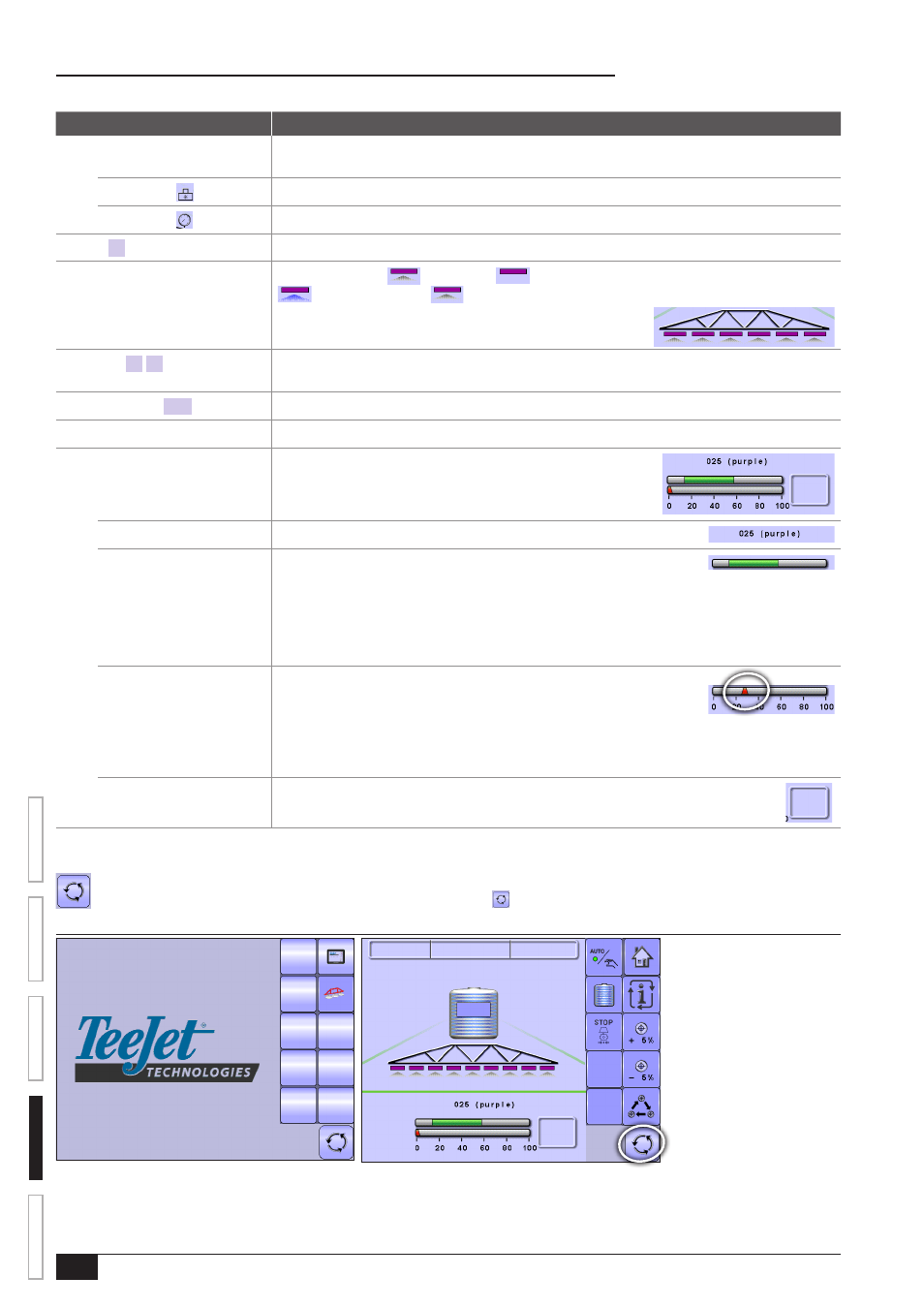
Master Screen
The Master Screen gives access to the systems currently available on your VT.
• To view the Master Screen options, select MASTER SCREEN KEY in bottom right corner of any screen.
Figure 4-3: Master Screen
Master Screen Key on Operation Mode Screen
C n t 1
0 . 0
0
0 l
0
b a r
0 . 0 0 h a
1 3 11
l / h a
k m / h