0 maintenance/service procedures - electric, Heat section, Single heating element – Reznor YDSA Operation Manual User Manual
Page 42: Electric heating operation, elements and controls, Service, Location
Form O-Y, PN 273647R1, Page 42
Contactors
Fuse Blocks
SCR Controller
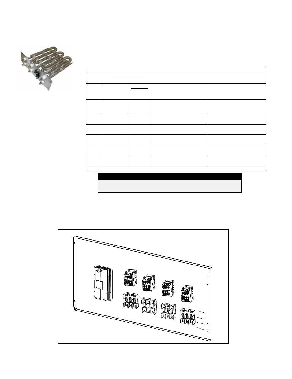
Electric Heat Control Panel
A call for mechanical heat will occur when the discharge air temperature is
5°F(2.8°C) below the active setpoint. When the OAT is below 65°F/18°C (Heating
Lockout SP), the unit enables the mechanical heat to maintain the active setpoint.
The modulated heat output will be set to 30% output and NO8 will be ON. The sys-
tem will remain in this state for 30 seconds. After the initial timer has expired, the unit
will stage as shown in the staging chart and the PID loop will activate. Stages should
be assumed cumulative from the previous stage.
Electric Heat Staging
PI Loop Control:
All Statements Must Be True To Activate or De-Activate.
All stages will have an adjustable min ON and OFF time.
Stage
Outputs
Increase
Inter-Stg
Timer
Activate
De-activate
(No timers to de-activate
except as shown.)
Stg 1
Y4 = 30% for
30 seconds
& NO8 = ON
DAT 5°F (2.8°C) below set-
point (Y4 Modulates, PI Loop)
Y4 < 10% Modulation & DAT
5°F (2.8°C) above setpoint for
10 mins
Stg 2
NO9 = ON
5 min
Y4 > 70% Modulation & DAT
5°F(2.8°C) below setpoint
Y4 < 55% Modulation & DAT
5°F(2.8°C) above setpoint
Stg 3
NO10 = ON
5 min
Y4 > 75% Modulation & DAT
5°F(2.8°C) below setpoint
Y4 < 65% Modulation & DAT
5°F(2.8°C) above setpoint
Stg 4
NO11 = ON
5 min
Y4 > 80% Modulation & DAT
5°F(2.8°C) below setpoint
Y4 < 70% Modulation & DAT
5°F(2.8°C) above setpoint
Stg 5
NO12 = ON
5 min
Y4 > 85% Modulation & DAT
5°F(2.8°C) below setpoint
Y4 < 75% Modulation & DAT
5°F(2.8°C) above setpoint
Stg 6
NO13 = ON
5 min
Y4 > 90% Modulation & DAT
5°F(2.8°C) below setpoint
Y4 < 80% Modulation & DAT
5°F(2.8°C) above setpoint
All parameters are factory level access.
Single Heating
Element
(Each heat
section includes an
assembly of single
elements)
6.0 Maintenance/Service Procedures - Electric Heat Section
Electric Heating
Operation, Elements
and Controls
Service:
Carefully clean all dust and dirt from the heating elements using a brush or steel wool. With a vacuum or air
hose, clean the inside of the cabinet especially the bottom and sides where dirt and dust will accumulate.
If replacement parts are required, check with your distributor and use only factory-authorized replacements.
Location:
See the control location illustration in
FIGURE 1, page 4, and FIGURE 29, shown below for the electric
heat section panel. The distribution blocks, fuses, contactors and optional SCR controller are mounted on the panel.
The quantities and locations of these items depend on the size of the unit.
To access the electric heat elements, remove two screws on the left side of the hinged electric heat control panel.
FIGURE 29 - Electric Heat Control Panel Illustration (NOTE: Danger High Voltage)
DANGER
High voltages are present on the Electric Heat Control Panel
components shown below in FIGURE 26.