0 maintenance/service procedures - gas, Heat section, 1 gas heat controls – Reznor YDSA Operation Manual User Manual
Page 32
Form O-Y, PN 273647R1, Page 32
5.0 Maintenance/Service Procedures - Gas Heat Section
This gas heat section will operate with a minimum of maintenance. To ensure long
life and satisfactory performance, a heater that is operated under normal conditions
should be inspected and cleaned at the start of each heating season. If the heater is
operating in an area where an unusual amount of dust or soot or other impurities are
present in the air, more frequent maintenance is recommended.
When any service is completed, be careful to reassemble correctly to ensure that no
unsafe conditions are created. When re-lighting, always follow the lighting instruc-
tions on the furnace.
WARNING
Turn off the power before performing maintenance procedures. Lock disconnect switch
in OFF position. When you turn off the power supply, turn off the gas at the external
manual valve. See Hazard Levels, page 2.
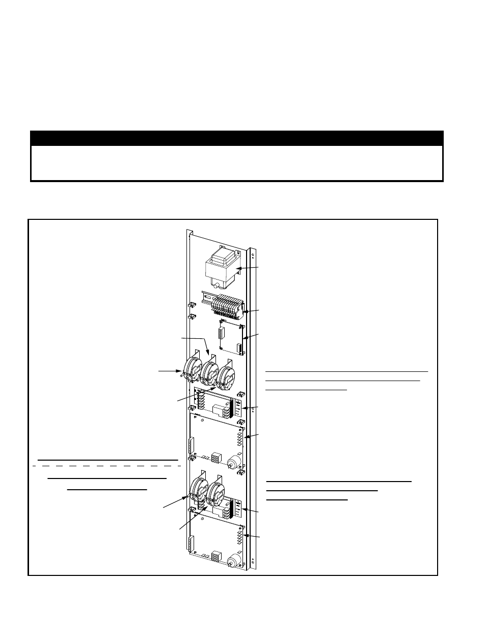
5.1 Gas Heat
Controls
75VA Transformer
Terminals
Venter Motor
Speed Controller
(AG73 & AG74)
Pressure Switches for Single Heat Section or
Right (first) Furnace in a Dual Heat Section
(See descriptions left.)
Relay (communicates with
the system controller)
DSI Control Module for
Single Heat Section or
Right (first) Furnace in
a Dual Heat Section
Pressure Switches for the Left (second)
Furnace in a Dual Heat Section
(See descriptions left.)
DSI Control Module for
the Left (second) Furnace
in a Dual Heat Section
Low Speed
Venter Switch
(AG73 & AG74)
Blocked Condensate
Switch (High Efficiency,
Condensing Furnace)
High Venter
(Combustion Air) Switch
Blocked Condensate
Switch (High Efficiency,
Condensing Furnace)
High Venter
(Combustion
Air) Switch
Relay (communicates with
the system controller)
Controls for all Gas Heat Sections
Additonal Controls for Dual
Gas Heat Sections
The gas heat section controls are located on the left wall of the gas heat section.
Check all wiring connections and verify sequence of operation.
FIGURE 23 - Gas Heat
Controls