5 coils and related components (cont'd), Optional modulating reheat (cont'd) – Reznor YDSA Operation Manual User Manual
Page 14
Form O-Y, PN 273647R1, Page 14
LED
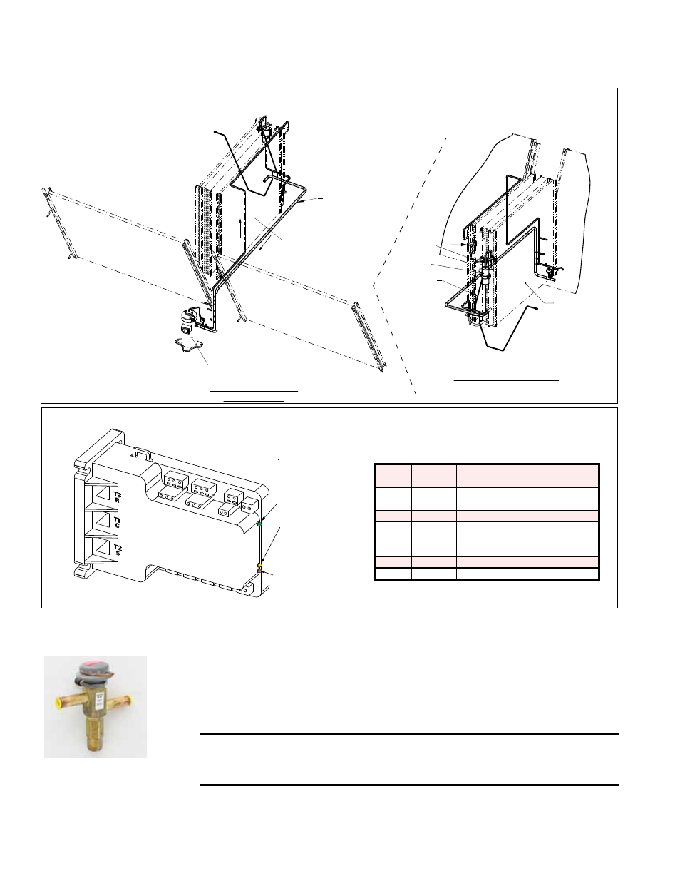
Color
LED
State
Indicates
Green Solid
Power (24VAC present at
power terminals)
Green Flashing Anti-short cycle timer is active
Yellow Solid
Unloader (Solenoid valve
is energized; compressor
capacity is 0.)
Red
Not lit
No abnormal operation alerts
Red
Flashing See Paragraph 7.2 (page 45).
M1
A1 A2
L1 L2
U2
U1
M2
V1 V2
P6
P5 P4
P3 P2
P1
C2
C1
C4
C3
24
VAC
24
COM
T6
T5 T4
T3 T2
T1
Power Light
(Green LED)
Compressor
Modulating
Solenoid Valve
Energized Light
(Yellow LED)
Alarm Light
(Red LED) - See
Paragraph 7.2
shown on page 45.
Compressor Digital
Controller for
Modulating Operation
FIGURE 15 - Digital Controller for DH Circuit Compressor, P/N 266067
Function: The hot gas bypass valve allows some of the refrigerant gas from the suc-
tion line to be re-routed directly to the evaporator coil providing for expanded com-
pressor modulation at low outside air temperatures. Hot gas bypass is only on the
non-modulating compressor circuit (Circuit B). See
FIGURE 16 on page 15.
Service: To check the hot gas bypass valve setting, connect a pressure gauge to the
suction line and block the entering air to the evaporator coil. Suction pressure will
drop, and the hot gas bypass valve should begin to open at a approximately 115 psi
and will be fully open at 95 psi. When the valve begins to open it will be hot to the
touch (see caution below).
CAUTION: Touching the operating hot gas bypass valve can cause
a burn. Use caution when checking and adjusting the valve. See
Hazard Levels, page 2.
If a hot gas bypass valve needs to be replaced, use only a factory-authorized
replacement for R-410A refrigerant. All refrigerant service should be done by a
qualified R-410A service technician.
Optional Hot Gas
Bypass Valve
(Option AUC8)
Hot Gas Bypass
Valve
3.0 Maintenance and Service Procedures - Unit & Cooling (cont'd)
3.5 Coils and Related Components (cont'd)
Optional Modulating Reheat (cont'd)
View from Compressor and
Condenser Section
Circuit A & B
Condenser Coil
Circuit B
Modulating
Compressor
Condenser Coil
Circuit
A
Evaporator Coil
with Intertwined
Circuits A & B
View from Cooling Cabinet Door
(Evaporator Coil Side)
Equilizer Tube
Evaporator Coil
Model YDHA 300 & 360 (Cabinet 3)
Model YDMA 300 & 360 (Cabinet 3)
Filter Drier
TXV Valves
FIGURE 14 - Optional
DH Circuit (Option
RPLE Low Enthalpy
Reheat Pump or
Option RPHE High
Enthalpy Reheat Pump