Reznor OH Unit Installation Manual User Manual
Page 9
Form I-OH, PN 120390 R5, Page 9
All manifold and feeder lines must run in a horizontal plane at an elevation above the
fuel intakes of the units. Extend feeder lines downward to fuel burner intakes.
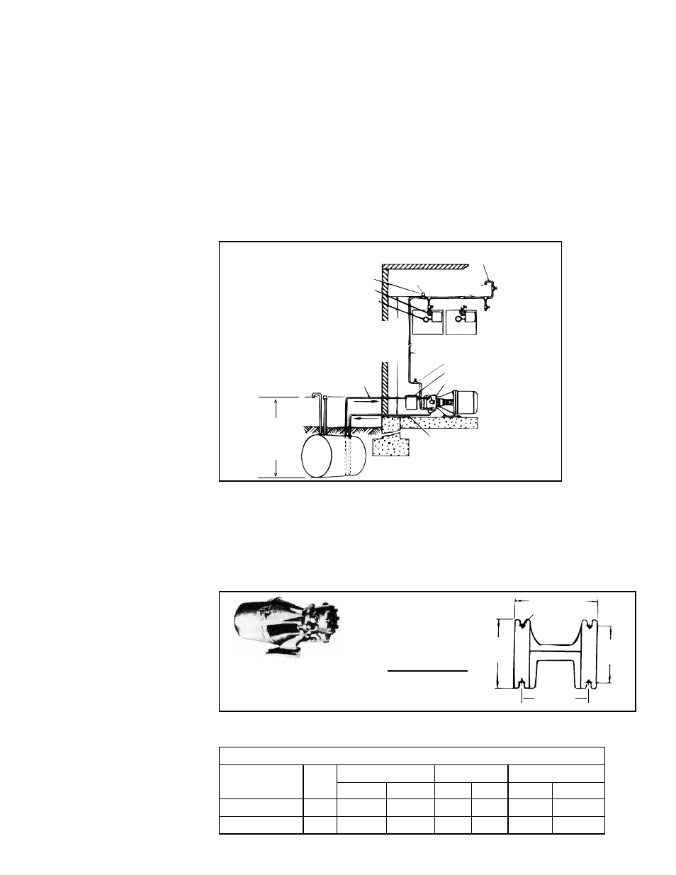
6.1.4 Pressurized System
A pressurized system is one in which a boost pump is used to supply fuel oil to a
manifold for which branch lines supply each heater. The end of the manifold is capped,
and the system is operated at a pressure not exceeding 3 psi at the first burner sup-
plied. BTU output in this type of system is determined by boost pump capacity and
the subsequent number of burners that can be supplied adequately by fuel oil. For
example, a 30 GPH booster pump will sustain eighteen 1.65 GPH burners. An optional
solenoid valve is recommended to protect burner pump seal against excessive pres-
sure. Optional pressure switch monitors nozzle pressure and will start booster pump
on pressure fall.
Boost pump operation in a pressurized system may be continuous or may be intermit-
tent when optional pressure switches are used.
6.1.5 Boost Pump Assembly (Option DA1 or DA2)
The boost pump is equipped with a motor and is supplied with a two-stage fuel unit
incorporating a regulator valve and strainer. The valve acts as a check to prevent loss
of oil supply between the boost pump and the burner, thus assuring instantaneous
starts following shutdown periods. Regulator valve also prevents excessive pressures.
Complete assembly with motor is approximately 15" (381mm) long, 7-1/2" (191mm)
high and 6-3/4" (171mm) wide overall.
Manifold Air Bleed -
highest point in line
Compound
Gauge
Maximum Intake Pressure
at Burner is 3 PSI
Pipe Cap
Manifold Line
Furnace
#3 etc
#2
#1
1/2 OD Tubing -
Return Line
Boost Pump
Auxiliary Filter
Shutoff Valve
1/2 OD Tubing
Tank
15 ft
(4.5M)
Maximum
Lift
35 ft
(10.7M)
Maximum
Lift
Pressure Switch (Opt DF1)
Solenoid Valve (Opt DD1)
1/2 OD
Tubing
- Inlet Line
FIGURE 7 -
Pressurized Supply
System (multiple
units)
Boost Pump will run
intermittently. See
Paragraph 6.1.5.
FIGURE 8 - Boost
Pump and Mounting
Bracket
5-7/8 (149mm)
4-7/8
(124mm)
4
(102mm)
4-3/4
(121mm)
R 11/64(4.4mm)
Boost Pump
Bracket
Mounting
Dimensions
(Bottom View)
Boost Pump
30GPH/70GPH
TABLE 7A - Maximum Horizontal Length from Boost Pump to Burner(s)
Boost Pump
GPH
1/2" OD Tubing
1/2" Pipe
3/4" Pipe
ft
M
ft
M
ft
M
Option DA1
30
175
53.3
300
91.4
1800
548.6
Option DA2
70
50
15.2
100
30.5
600
182.9
Boost Pump Capacities
Maximum Height from Boost Pump to Burner -- 35 feet (10.7M).