4 major components – Reznor OH Unit Installation Manual User Manual
Page 15
Form I-OH, PN 120390 R5, Page 15
7.4 Major Components
Motors - See electrical characteristics in TABLE 9. The fan motor is totally enclosed
and is equipped with internal overload protection.
Motor
Size
HP Volts Amps RPM
Fan
95
1/8 115
2.7 1050
140, 190 1/4 115
3.7
850
140, 190 3/4 115
11
1725
Std 1-Stage Burner Pump
95, 140,
190
1/7 115
2
3450
Opt 2-Stage Burner Pump
1/7 115
2
3450
Optional Boost Pump
1/8 115
5.8 1725
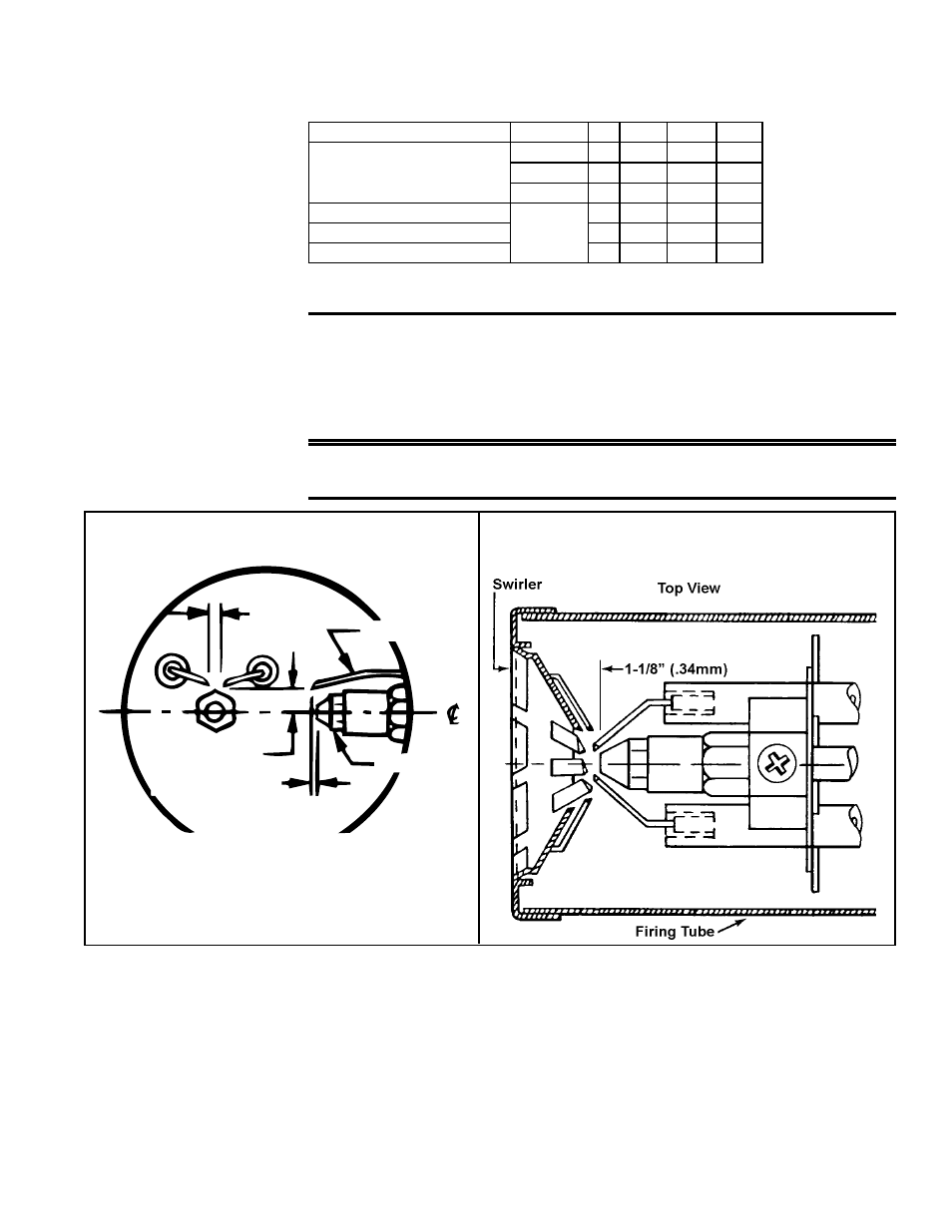
Electrodes and Nozzle Location
IMPORTANT: Check the electrode adjustment prior to firing
the unit. Electrodes are adjusted at the time of manufacture.
However, they should be checked at time of installation to be
sure that they are still set as illustrated in FIGURES 15 and
16.
CAUTION: Turn off main electric supply switch before
attempting to check or adjust electrodes.
FIGURE 16 - Nozzle Position in Relation to
Burner Head
FIGURE 15 - Electrode Gap for Beckett
Burner (Front View and Side View)
Gap -
1/8 (3.1mm)
Electrode
Nozzle
0 to 1/16
(1.6mm) ahead
7/16 (11mm) above
ELECTRODE
ADJUSTMENTS
Burner Pump
This oil-fired heater has either a standard single-stage, 3450 RPM pump or an
optional two-stage, 3450 pump (Option BZ1). Review the burner pump illustra-
tion,
FIGURE 17, for port, bleed, inlet, regulator, and bypass plug locations.
NOTE: Bypass plug must be inserted when return connection is made by two-
pipe supply system.
Pump Pressure Check (See Paragraph 8.1) - If a pressure check is made, use either
the gauge port or nozzle port. Do not use easy flow bleed valve port. The easy flow
bleed valve port contains pressure higher than operating pressure.
Setting pump
pressure with gauge in the easy flow bleed valve port results in WRONG operat-
ing pressure.
TABLE 9 - Electrical
Characteristics of
Motors