Maintenance and service (cont'd), 3 troubleshooting (cont'd) – Reznor OH Unit Installation Manual User Manual
Page 26
Form I-OH, PN 120390 R5, Page 26
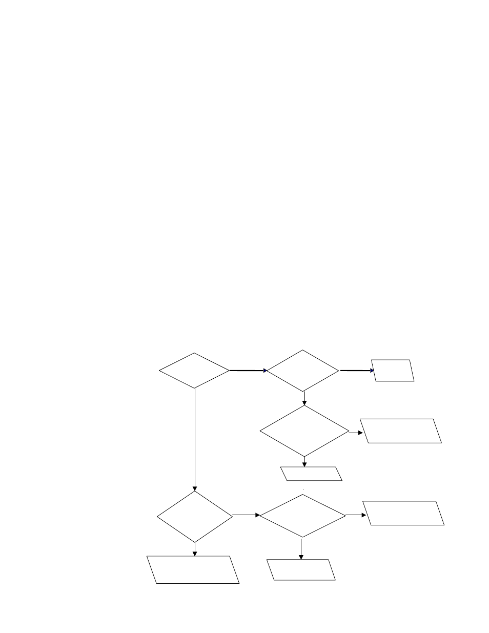
Does the fan
operate?
Are the heat
exchanger surfaces
and/or the fan blades
covered with
dirt?
Clean the heat
exchanger and fan.
See Paragraphs 9.2.1 and .4.
Remove ducts or
deflector from heater.
Check for 115
volts across fan leads.
Is voltage
read?
Replace fan
motor.
Check for 115 volts
across Terminals 1 & 2.
Is voltage
read?
Replace fan and limit
controls assembly.
See
FIGURE 18, page 16.
Check wiring.
YES
NO
YES
NO
YES
NO
YES
NO
YES
NO
Have ducts or
air deflectors
been added ?
Replace fan and limit
controls assembly.
See
FIGURE 18, page 16.
** High temperature limit
cycles when internal tem-
perature exceeds nonad-
justable limit setpoint (Size
95, 145°F; Sizes 140 and
190, 160°F). Cause must
be found and corrected for
heater to function safely/
properly.
9.3.2 Troubleshooting
Guide - High
Temperature Limit
Cycles **
9.3.1 Troubleshooting
the Oil Burner
(cont'd)
9. Maintenance
and Service
(cont'd)
9.3 Troubleshooting
(cont'd)
The control relay should pull in. If not, make sure that the wiring connections are
secure. If wiring connections are secure, check that the cad cell which controls the
safety lockout timing on ignition is not seeing too much stray light. Check the cad
cell by starting the burner and disconnecting both cad cell leads from the control
FF terminals. Jumper the FF terminals to keep the burner operating. Measure the
ohms resistance across the cad cell leads as it views the flame. This should be
1600 ohms or less. A preferred reading is 300-1000 ohms. Next, with the meter
still connected to the cad cell leads, turn the burner off. The dark condition should
give a reading of 20,000 ohms or infinity. If the reading is lower, let the refractory
cool down or look for stray light that might be entering the burner through the air
inlet, or around the transformer baseplate. If the cad cell is not performing within
these guidelines, replace it. If the wiring connections are secure and the safety
lock timing and cad cell are functioning properly, replace the primary control.
If the primary control relay pulls in and then locks out again quickly, check the
safety lockout timing. The safety lockout timing can be checked by removing one
of the F (cad cell) leads from the control. Count the seconds until the control locks
out. The time should be close to the rating plate specification found on the control
body.
If the primary control relay pulls in erratically and chatters, check the wiring con-
nections and verify that the heat anticipator setting of the thermostat matches the
24 volt current draw. Erratic operation can sometimes be traced to improper antici-
pator settings of the primary control. These settings are typically .2 or .4 amps
(printed on the side of the control). Measure this value by connecting your multi-
tester in series with one of the TT lead and reading the value of the appropriate
milliampere scale. If the wiring connections are secure and the anticipator settings
are correct, replace the primary control.
If the primary control relay pulls in, but the motor fails to start, measure the voltage
between the neutral lead and the primary control lead for the motor. A severe volt-
age drop here would indicate that the relay switch contacts are defective. Replace
the primary control.