Length = 6 ft - (.75 x lift) – Reznor OH Unit Installation Manual User Manual
Page 7
Form I-OH, PN 120390 R5, Page 7
part of a burner, connect a pressure relief valve into the discharge line between the
pump and the shutoff valve and arrange to return surplus oil to the supply tank or to
bypass it around the pump, unless the pump includes an internal bypass.
Any fuel oil line incorporating a heater shall be provided with a relief valve arranged
to discharge to the return line when any valve, pump, or other device may prevent the
release of excessive pressure because of the expansion of the oil when heated.
Where oil is supplied to a burner requiring uniform flow by gravity feed and a constant
level valve is not incorporated in the burner assembly or the oil is not supplied by an
automatic pump, install a constant level valve in the supply line at the gravity tank or as
close as practical, to ensure uniform delivery of oil to the burner. The vent opening of
the constant level valve should be connected by piping or tubing to the outside of the
building, unless the constant level valve is provided with an anti-flooding device. Do
not connect the vent piping or tubing of constant level valves to tanks or tank vents.
Prior to entering enclosures, such as vaults or pits, where pumps and accessories are
installed, provide for adequate ventilation.
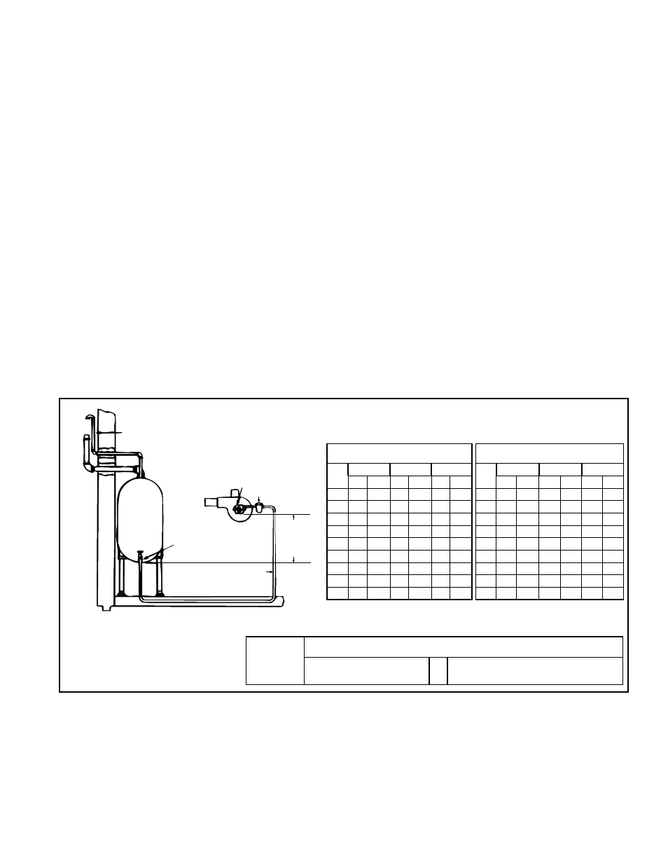
6.1.1 Standard Single Stage Burner Pump with Single Supply Pipe
The standard burner is equipped with a single-stage, 3450 RPM pump with the lift
capacity shown in
FIGURE 4. Maximum lift is 8 ft (2.4M). Fittings, valves and filters
will reduce total line length allowed. Check component manufacturer's information for
equivalent length reduction required to compensate for pressure loss. A one-pipe sup-
ply system must be absolutely airtight, or leaks and/or loss of prime may result. Follow
instructions in Paragraph 8.2, Check-Test-Start (Operating Procedure) to bleed the
line. Bleed for 15 seconds after last air is seen from easy flow bleed valve to be certain
lines are air free.
Fuel Unit
Auxiliary Filter
Maximum
One Pipe
Lift
8 ft (2.4M)
Inlet
Shutoff Valve
Oil
Tank
1-1/4 (32mm) minimum
Fill
Pipe
Air
Vent
FIGURE 4 - Single Pipe Supply System (single-stage burner pump)
Maximum Horizontal Line Length (ft) by
Heater Size and Size of Tubing
Maximum Horizontal Line Length (M) by
Heater Size and Size of Tubing
Lift
95
140
190
Lift
95
140
190
(ft)
3/8" 1/2" 3/8" 1/2" 3/8" 1/2"
(M)
3/8" 1/2"
3/8" 1/2" 3/8" 1/2"
0
822 3158 556 2222 423 1667
0.0
251
963
169
677
129 508
1
719 2763 486 1944 370 1458
0.3
219
842
148
593
113
444
2
616 2368 417 1667 317 1250
0.6
188
722
127
508
97
381
3
514 1974 347 1389 264 1042
0.9
157
902
106
423
80
318
4
411 1579 278 1111 211 833
1.2
125
481
85
339
64
254
5
308 1184 208 833 158 625
1.5
94
361
63
254
48
191
6
205
789 139 556 106 417
1.8
62
240
42
169
32
127
7
103
395
69
278
53
208
2.1
31
120
21
85
16
63
8
0
0
0
0
0
0
2.4
0
0
0
0
0
0
Length =
6 ft - (.75 X Lift)
(.0086 for 3/8" tubing or
.00218 for 1/2" tubing)
X
(Firing Rate in GPH - OH95, .085;
OH140, 1.25; OH190, 1.35)
Formula for determining figures (ft) in
TABLE 5 above.
TABLE 5 - Maximum Horizontal Line Length
(ft/M) with a Single Pipe Supply System
6.1.2 Two-Pipe Supply System with Standard Single-Stage Pump
or Optional Two-Stage Pump
A two-pipe supply system may be used with the standard burner pump or with a two-
stage pump if Option BZ1 was ordered. The two-stage pump provides dual pumping
gears. To install the two-pipe supply system, remove the 1/4" plug from the return line
port and insert the 1/16" bypass plug (Shipped with the burner pump; see
FIGURE
17, page 17.). Attach the inlet and return lines. Always terminate the return line 3 to 4
inches (76 to 102mm) above the supply line inlet. See
FIGURE 5.