Electrical supply and connections, 1 general, 2 supply and line wiring – Reznor OH Unit Installation Manual User Manual
Page 13
Form I-OH, PN 120390 R5, Page 13
6.2.2 Combustion Air
WARNING: Exercise care to ensure that an adequate supply of
combustion air is available and free to enter the air openings
on all units.
Openings equal to one inch square per each 1,000 BTUH
should be used to allow combustion air to enter the room
where the heater is installed.
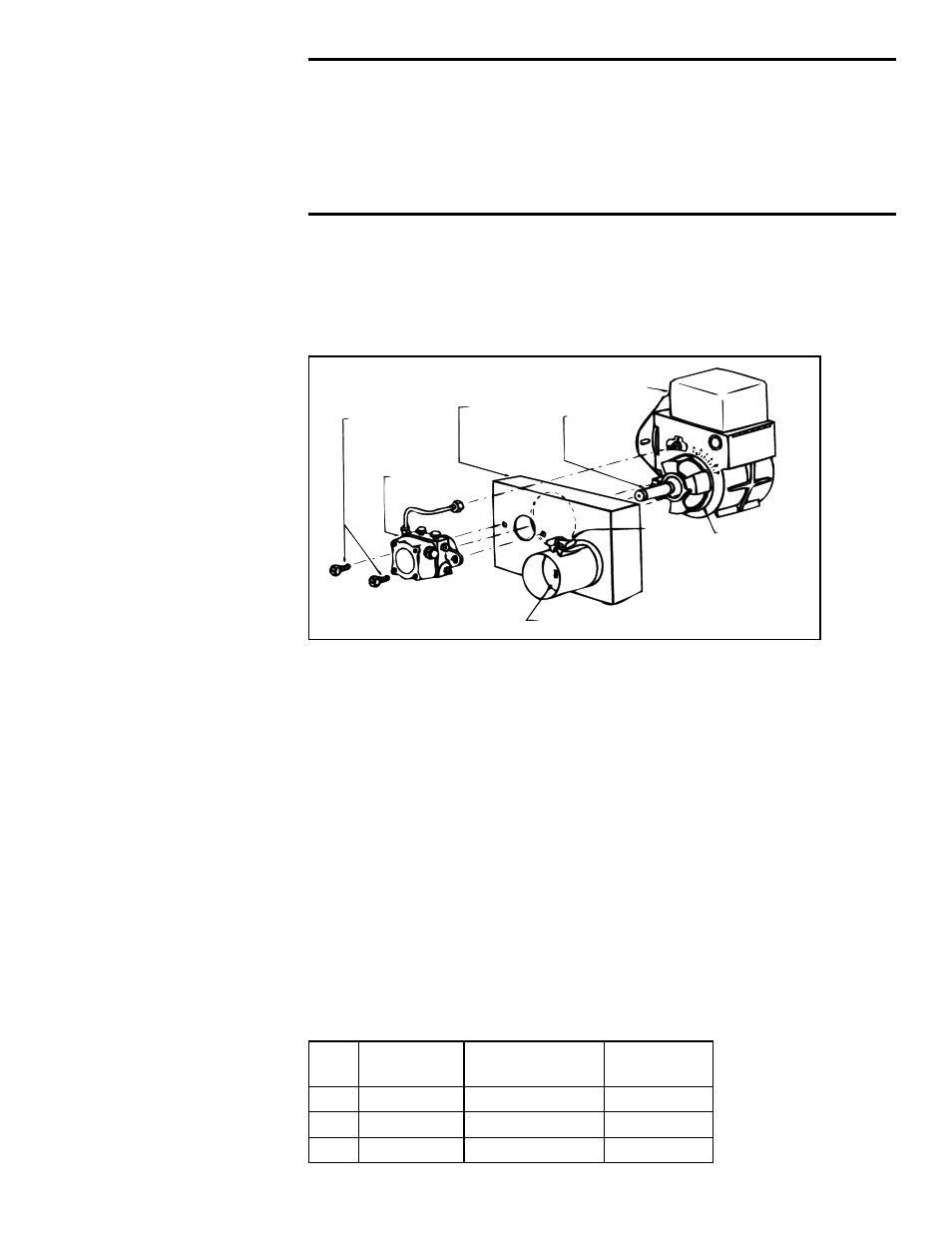
R.W. Beckett
Model AF Burner
Adhesive-
backed
Gasket
Air
Damper
Adjust-
ment
Air Damper
Pump
Mounting
Screws
Fuel Unit
Outside
Combustion
Air Intake
Assembly
Extra-long
Coupling
FIGURE 12 - Optional
Outside Combustion
Air Intake Adapter,
Option DE1
Optional Outside Combustion Air Intake Adapter Kit, UL Listed,
Option DE1 (shipped separately) (Not available for Canadian
installation.)
The combustion air adapter will provide outside air for combustion. Follow the manu-
facturer's instructions furnished with the kit.
7. Electrical
Supply and
Connections
7.1 General
All wiring must be done in accordance with the National Electric Code or CSA Standard
C22.1, Canadian Electrical Code, Part 1, and local ordinances. In many localities, No.
14 wire run in rigid conduit must be used, but where permissible, two and three wire BX
is recommended, particularly for connections to the controls and burner motor. A cutoff
switch for the main 115 volt line to the burner should be mounted on a fireproof wall in
an accessible place close to the burner.
The heater is equipped with low voltage controls (24V) for thermostat control. See
separate instructions for any optional equipment provided.
7.2 Supply and Line
Wiring
TABLE 8 - Electrical
Ratings, 115V, 60 Hz
Check the rating plate on the heater for supply voltage and current requirements. A
separate line voltage supply with fused disconnect switch should be run directly from
the main panel to the heater, making connection to leads in the junction box. All exter-
nal wiring must be within approved conduit. See wiring diagram in the heater junction
box. Conduit from the disconnect switch must be run so as to not interfere with heater
service access.
All replacement wiring must be type SF, SEWF, TW, TEW or equivalent. Use 18 gauge
wire for control circuits; 14 gauge or larger, depending on current requirements, for line
connections.
OH
Size
Total Current
Amperes
Minimum Circuit
Ampacity
Minimum
Fuse Size
95
6
8
15
140
7
9
15
190
7
9
15