Maintenance and service, Commissioning and startup (cont'd), 1 maintenance requirements – Reznor OH Unit Installation Manual User Manual
Page 20: 2 maintenance procedures, 2 check-test- start (operating procedure cont'd)
Form I-OH, PN 120390 R5, Page 20
9. Maintenance
and Service
The service and troubleshooting information in this section is designed to assist a
qualified service person.
9.1 Maintenance Requirements
Like all quality equipment, this oil-fired unit heater will operate with a minimum of main-
tenance. However, to ensure long life and satisfactory performance, the following ser-
vice regimen is recommended.
Heaters should be inspected once every four months where the equipment is operating
under normal conditions. If the heater is located in an area where an unusual amount
of dust or soot or other impurities are contained in the air, more frequent inspection
is recommended. Check the motor for cleanliness. Remove dirt and grease from the
outside of the motor, and especially around the shaft. Keep air openings free of grease
and dirt. The heat exchanger should be checked at least once a year and more often
in areas where the air is heavily dust laden.
9.2 Maintenance
Procedures
9.2.1 Cleaning Combustion Chamber, Heat Exchanger, and Flue
Pipe
WARNING: Turn off electric power before inspecting or
cleaning this heater.
Instructions for removing soot from the combustion chamber/heat
exchanger
1. On the burner end of the heater, locate the small exhaust door panel underneath
the burner tray. See
FIGURE 22. On Canadian Models, there is a screw (not shown
8.2 Check-Test-
Start (Operating
Procedure
cont'd)
8. Commissioning
and Startup
(cont'd)
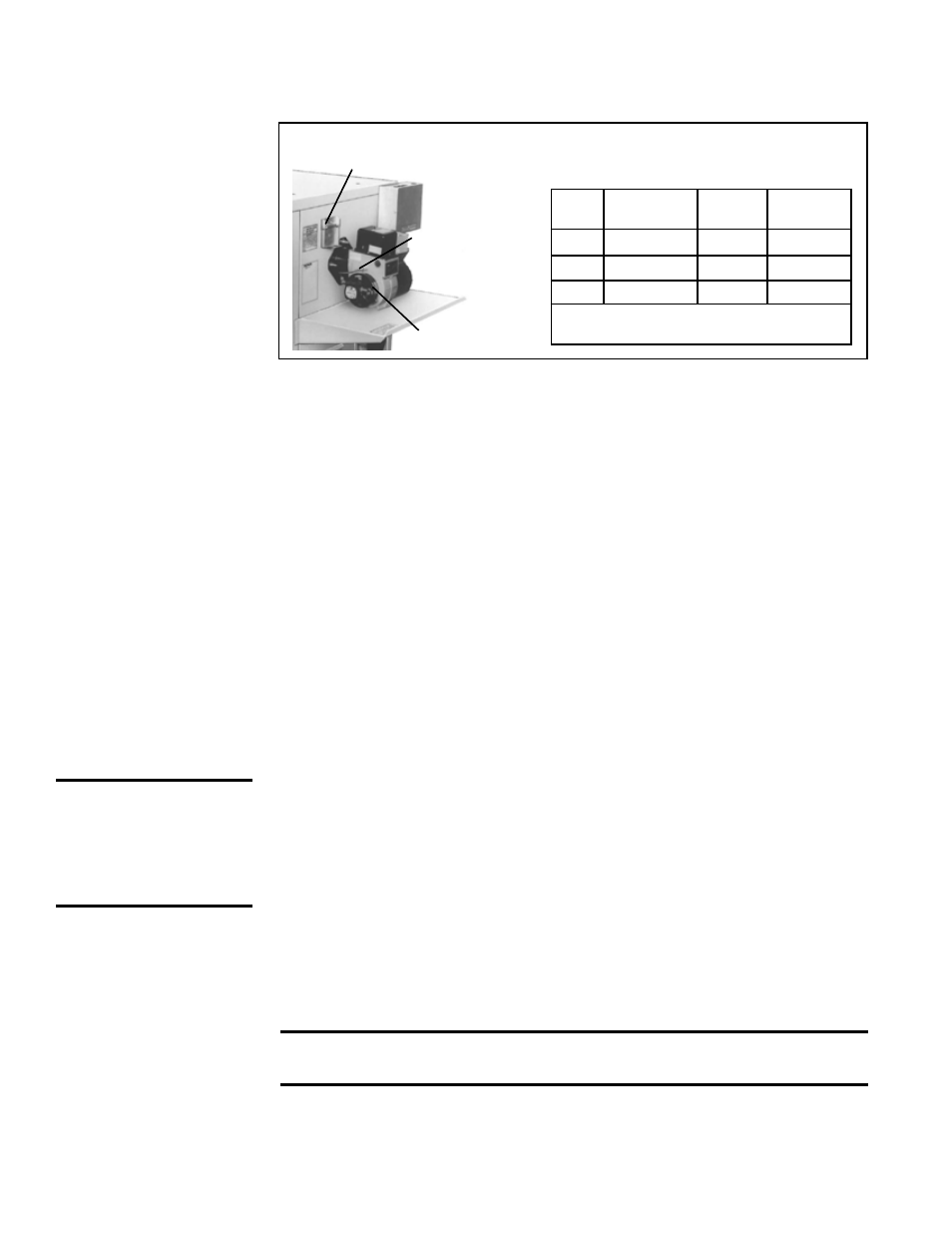
Air Band
Observation Door
Air Shutter
FIGURE 21 - Combustion Air Band and Air Shutter Settings
Size
Air
Shutter
Air
Band
CO2
Range
95
#6
#0
9-11%
140
#6
#0
10-12%
190*
#7-1/2
#0
11-13%
*Size 190 manufactured before 6/96 had
same settings as Size 140.
TABLE 11 - Settings
these settings will result in a CO
2
level shown in the tabled ranges. However, cer-
tain field conditions may require a change. In order to determine if the air setting
needs to be adjusted, a smoke tester and CO
2
analyzer are required.
Air Adjustment Procedure:
1) Service and clean the burner, combustion chamber, and heat exchanger if
necessary.
2) Operate the unit for at least 10 minutes.
3) Adjust the overfire draft to read between -0.01" to -0.02" w.c. Draft readings in the
breaching will be higher depending on the flue passages of the heater. The more
restrictive and lengthy the flue, the higher the draft necessary to obtain accepted
overfire conditions.
4) Follow the instructions of the manufacturer of the smoke tester and take a smoke
reading. Adjust the combustion air to obtain a preliminary reading of about a No. 3
smoke spot. Then readjust the air until a reading between No. 0 and No. 1 (trace
smoke) is achieved. Do not open the air adjustment more than absolutely neces-
sary to obtain a trace or No. 0 smoke spot.
5) Follow the instructions of the manufacturer of the CO
2
gas analyzer and take a
CO
2
sample. Open the air shutter until the CO
2
level lowers by 1%. The CO
2
read-
ing should fall within the range specified in the table shown in
FIGURE 21. Your
burner is now set for optimum but stable efficiency.
WARNING: Turn
off electric power
before inspecting
or cleaning this
heater.