Mechanical (cont'd), 1 fuel tank and supply lines (cont'd), Option df1, shipped separately) – Reznor OH Unit Installation Manual User Manual
Page 10: Boost pump pressure switch, 5 boost pump assembly (option da1 or da2) (cont'd)
Form I-OH, PN 120390 R5, Page 10
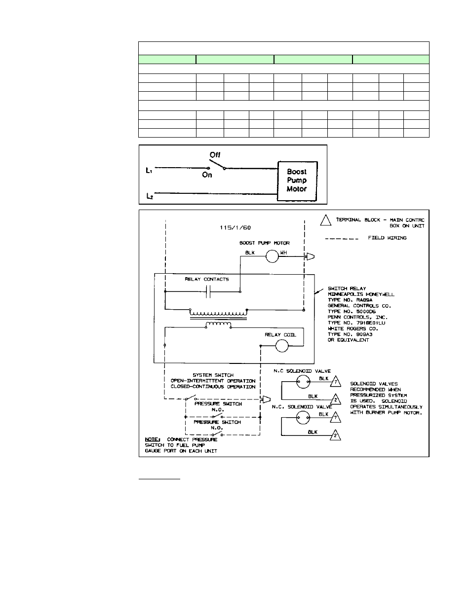
FIGURE 9 - Boost
Pump Wiring for
Constant Operation
(Loop System,
Paragraph 6.1.3)
FIGURE 10 - Boost
Pump Wiring for
Intermittent Operation
(Pressurized System,
Paragraph 6.1.4)
TABLE 7B - Maximum Horizontal Length from Oil Supply to Boost Pump by Line Size
Line Size
1/2" OD Tubing
5/8" OD Tubing
1/2" Pipe
Maximum Horizontal Length from Oil Supply to Boost Pump (ft)
Lift
0-7 ft
10 ft
15 ft
0-7 ft
10 ft
15 ft
0-7 ft
10 ft
15 ft
Opt DA1, GPH30
64'
49'
24'
100'
100'
65'
100'
100'
100'
Opt DA2, GPH70
44'
34'
17'
100'
95'
48'
100'
90'
65'
Maximum Horizontal Length from Oil Supply to Boost Pump (meters)
Lift
0-2.1 M
3 M
4.6 M
0-2.1 M
3 M
4.6 M
0-2.1 M
3 M
4.6 M
Opt DA1, GPH30
19.5M
14.9M
7.3M
30.4M
30.4M
19.8M
30.4M
30.4M
30.4M
Opt DA2, GPH70
13.4M
10.4M
5.2M
30.4M
29M
14.6M
30.4M
27.4M
19.8M
6. Mechanical
(cont'd)
6.1 Fuel Tank and
Supply Lines
(cont'd)
Boost Pump Pressure Switch
(Option DF1, shipped separately)
Application - Intermittent boost pump operation in a pressurized system (Para-
graph 6.1.4).
This low voltage, normally open type switch closes at approximately 50 psi. Maximum
allowable pressure is 150 psi.
One is required for each burner. The switch is specifi-
cally designed for fuel oil and includes a 1/8" male pipe thread connector and screw
terminals.
A manual switch, for initial starting (or continuous operation) is recommended for instal-
lation in the low voltage circuit.
Pressurized piping systems must not exceed 3 psi. An oil solenoid valve (Option DD1)
is recommended at each unit to prevent seal damage should the pressure for any rea-
son exceed the maximum of 3 psi.
6.1.5 Boost Pump Assembly (Option DA1 or DA2) (cont'd)