Hardware setup, Basic setup and connections – PRG Mbox Designer Manual 3.9 User Manual
Page 39
MBOX
®
MEDIA SERVER USER MANUAL
31
HARDWARE SETUP
Basic Setup and Connections
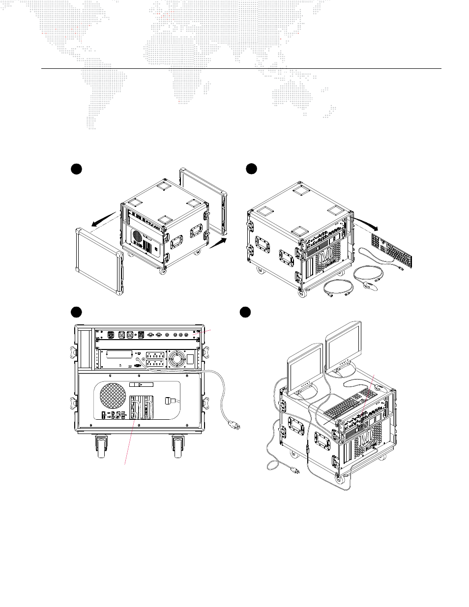
To interconnect the case components:
Step
1. Remove front and back covers from case (Figure 2-4).
Step
2. Remove keyboard and trackball from case.
Step
3. At rear of case, verify that Monitor (2), USB (3), Ethernet (2), Video In (2) and Power cables are connected to
computer.
Figure 2-4: Removing Covers and Components
Step
4. At front of Dual I/O module, connect local monitor data cable to DVI connector labeled "Preview."
Step
5. Connect local monitor power cable to UPS or to local AC power service.
Step
6. Connect UPS power cable to local AC power service.
Step
7. Connect stage outputs and other Mbox Extreme servers (if required) according to the following sections.
SIT E WIRING
FA ULT
OUT PU T: 1 20V 50/ 6 0 Hz
S E NSIB ILIT Y
I NP UT
RE S ET
P USH T O
P ROT ECT OR
O VERLOAD
US B P ORT
(COMPOSI TE)
Y IN
BALANCED AUDI O OUT
ETHERNET
LEF T
RIGHT
SMPTE IN
MIDI IN
M IDI OUT
SDI IN
R - Y IN
B - Y IN
Remove covers
1
2
Remove components
Monitor, USB, and Ethernet Connections
Connect monitor
AC cable to UPS
To AC Power
Connect monitor
data cable to DVI
3
Verify rear connections
4
Connect monitor and power source
Preview
(permanently connected - do not alter)
To AC Power
Auxiliary Input
Connections
or local AC