Components, Mbox extreme case assembly, Ba p re v ie w 1 – PRG Mbox Designer Manual 3.9 User Manual
Page 15: V g a 1, D v i 1 rdm tx, Out in dmx rx rdm rx, T m in out, Mbox, Media server user manual 7
MBOX
®
MEDIA SERVER USER MANUAL
7
COMPONENTS
Note: This section deals with Mbox Extreme hardware and may not be pertinent to a computer-only installation.
Mbox Media Server Training Video Chapter 1: Introduction
Mbox Extreme Case Assembly
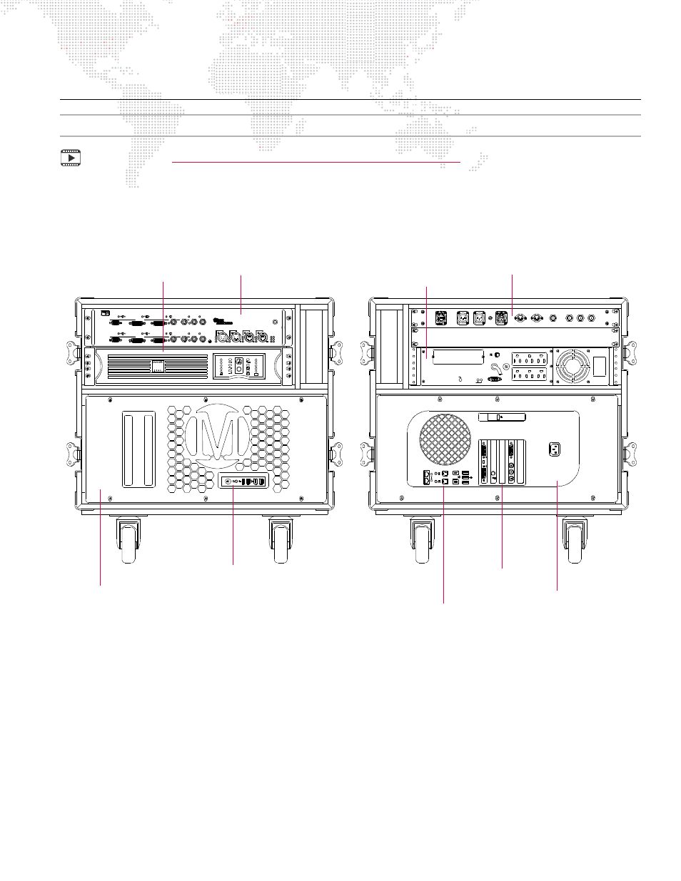
The following illustrations show the main case components for the Mbox Extreme v3 hardware:
Figure 1-2: Mbox Extreme v3 Single Rack Unit
* Refer to
** Refer to
*** Refer to
SITE WIRIN G
FAULT
OUT PUT: 120V 50/60 Hz
SENSIBILITY
IN PU T
R ESET
PUSH TO
PRO TECTOR
OVERL OAD
U SBPOR T
2
out
op
tic
al
audi
o
LEFT
RIGHT
SM PTE IN
MIDI IN
MIDI OUT
SDI IN
R - Y IN
B - Y IN
1
in
2
1
(COMPOSI TE)
Y IN
BALANCED AUDIO OUT
ETHERNET
EDIDCAP
TUR
E
B
A
P RE V IE W 1
SDI 1
OUT
PUT1
PREVIEWDIM
EDIDCAP
TUR
E
A
B
Rx
V G A 2
D V I 2
P RE V IE W 2
SDI 2
STAGEBLACK
OUT
V G A 1
STAGEBLACK
OUT
PREVIEWDIM
OUT
PUT2
D V I 1
RDM Tx
INPUT 1
GENLOCK 2
INPUT 2
PORT1
PORT 2
B
A
ETHERNET
D ual I/O Module
USB
OUT
IN
DMX Rx
RDM Rx
GENLOCK 1
DMX
T M
IN
OUT
USB
COMPUTER
Tx
LINK
M O D EL 20 -980 4 -010 0
POWER
ACTIVE
ACTIVE
Mac Computer ***
(under faceplate cover)
UPS Power Unit
Dual I/O Module *
Headphone, FireWire,
and USB Connections
Mac
Computer ***
Auxiliary Input Panel **
UPS Power Unit
FRONT VIEW
REAR VIEW
Ethernet, Audio, USB,
and FireWire Connections
Graphics, Genlock,
and Capture Cards