Heli-Max HMXE0250 User Manual
Page 9
9
❏
3. Apply thread locker to one 3x12mm socket head cap
screw. Install the screw and washer as shown above.
Repeat on the opposite side of the frame.
❏
4. Apply thread locker to one 3x14mm socket head cap
screw. Install the screw and washer as shown above. Repeat
on the opposite side of the frame.
❏
5. Slide the servo frame in-between the lower frames and
onto the upper frames. Install a 3x12mm self-tapping screw
into the top of the frame as shown above. Repeat for the
opposite side.
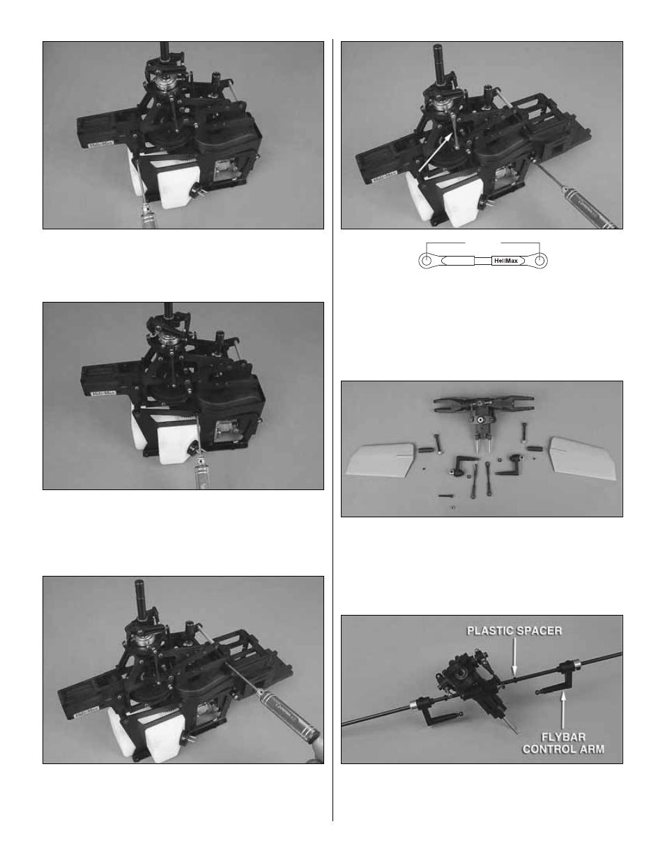
❏
6. Install the silver 3x6mm silver Phillips screw into the
lower part of the servo frame as shown above. Remove the
two bellcrank to swash linkages and verify they are 51mm
long. Go ahead and re-install the linkages now.
MAIN ROTOR HEAD ASSEMBLY AND INSTALLATION
Bag 1 Contents: Flybar Control Arm [4x6x2.5mm Plastic
Spacer (2), Washout-Flybar Pushrod (2), Flybar Control
Arm (2), 5x4mm Set Screw], Flybar Paddles [Flybar Weights
(2), 3x3mm Set Screws (2), Flybar Paddles .50 Sized (2)],
Main Head Assembly, 4x30mm Cap Screw (2), 4mm
Locknut (2), 3x20mm Cap Screw, 3mm Locknut
❏
1. Slide the 4mm flybar (found in tail boom bag 8) through
the flybar carrier bearings and slide a plastic bushing on from
each side. Next slide the control arms onto the flybar as shown
in the picture above. (The set screws will face upwards.)
51mm
(
S
ketch not to
s
c
a
le)