Heli-Max HMXE0250 User Manual
Page 6
6
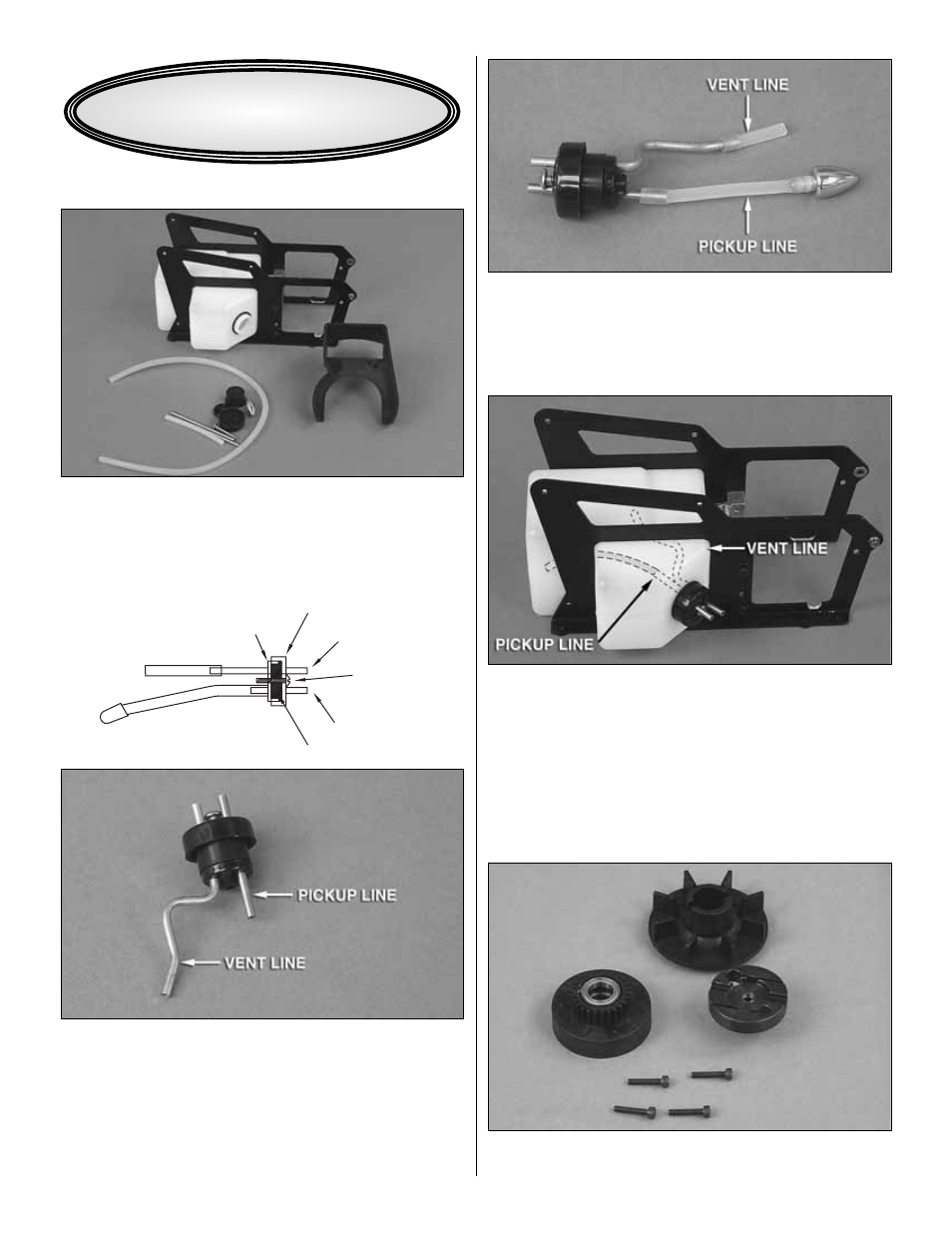
LOWER FRAME AND TANK
Bag 10 Contents: Main Frame Assembly (Engine Mount
and Fuel Tank Installed), Fuel Stopper, Brass Tubing,
Silicone Fuel Line, and Stopper Screw, Lower Fan Shroud.
❏
1. Slide the short brass tubing through the front cap. Slide
the rubber fuel tank stopper over the brass tubing from the
back side. Install the rear cap. Insert the long pre-bent piece of
brass tubing through the rear cap and through the rubber
stopper. Leave 1/2" [12.7mm] of brass tubing protruding from
the front of the cap. Install the 4mm self-tapping screw through
the front cap and into the rear cap (Start the screw into the
cap. Do not tighten until it has been installed into the fuel tank).
❏
2. Cut the clunk line to a length of 60mm and slide it onto
the short brass tubing. Slide the fuel tubing over the clunk. Cut
a piece of the larger silicone tubing to 30mm with an angled
cut as shown above. Install on the vent line. Hint: Use a
marker to identify the pickup line later.
❏
3. Rotate the vent line against the pickup line to make it
easier to install. Slide the fuel line assembly into the fuel
tank and align the vent line with the top of the tank (if you
find it difficult to see inside the tank, hold it up to a bright
light). Tighten the 4mm fuel tank stopper screw until you feel
it begin to compress. Do not overtighten this as you may
strip the rear cap.
ENGINE
Bag 3 Contents: Clutch Bell, Fan, Clutch, Engine Mount
From Bag 10: Screws (3x16mm Socket Head Cap Screw)
AS VIEWED FROM THE TOP
REAR CAP
FRONT CAP
VENT
4mm
S
CREW
FUEL PICKUP LINE
RUBBER
S
TOPPER
ASSEMBLY INSTRUCTIONS