Channel radio setup – Great Planes Giant Aeromaster Kit - GPMA0502 User Manual
Page 45
The aileron connecting pushrods are assembled following
the same method used to assemble the N-struts If you
installed aileron servos in the top and bottom wing proceed
to the Set the Control Throws section
D 1 Cut the two 5/8" x 12" hardwood aileron connection
pushrods to the shape shown on the fuselage plan Use a
sanding bar loaded with 150-grit sandpaper to round the
tips to the desired shape The struts can be covered with
MonoKote film covering or painted with a fuelproof paint
such as LustreKote spray paint.
D 2 Use a 5/64" drill bit to drill a hole 1/2" deep, centered
in the notch, at both ends of the connecting pushrod.
D 3. Thread two 4-40 nuts close to the head of two of the
4-40 x 1" machine screws Mix a small amount of
30-minute epoxy and apply a small amount to the last 1/2"
of threads on the machine screws Then thread the
machine screw halfway into the end of the connecting
pushrod Install only the two machine screws with the nuts
installed.
D 4 After the epoxy has cured, thread the nut against the
connecting pushrods and use a cut-off wheel or hack saw
to cut off the head of the machine screw Unscrew the nut
from the machine screw The nut will clean up the threads
as it is removed.
D 5 After all the nuts have been removed, thread the nuts
onto the remaining two 4 40 x 1" machine screws and
install them in the remaining ends of the struts following the
same procedure as before.
D 6. Place the connecting pushrods over the plan to
determine which end will go at the top Thread a 4-40 nut
on that end Thread a 4-40 metal clevis onto both ends of
the two connecting pushrods. The nut will be used later to
lock the clevis in position.
D 7 Attach the connecting pushrods to the ailerons on
both wings Adjust the aileron connecting pushrods so
that the ailerons are in the same position on the top and
bottom wing.
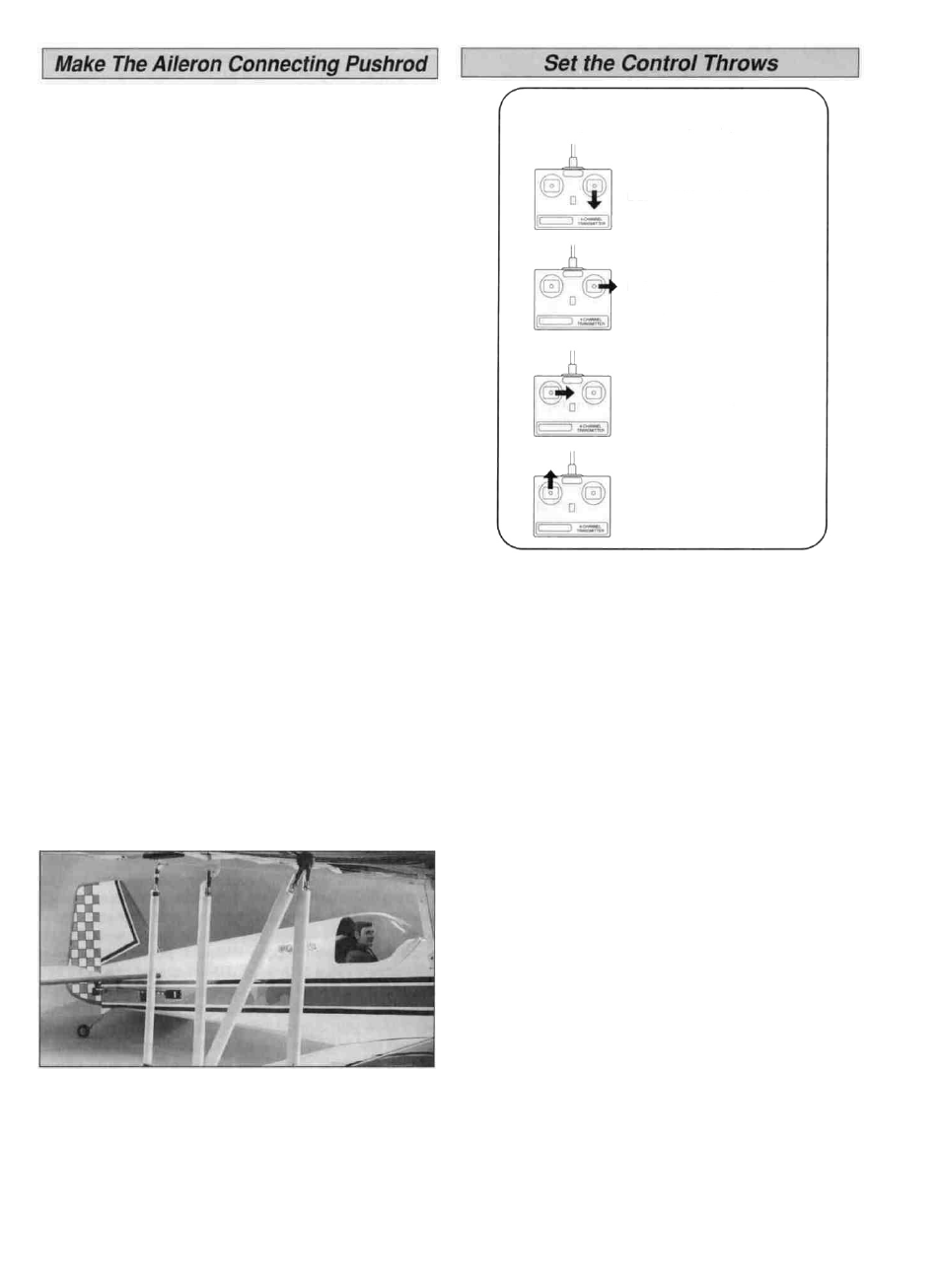
ELEVATOR MOVES UP
RIGHT AILERON MOVES UP
LEFT AILERON MOVES DOWN
RUDDER MOVES RIGHT
CARBURETOR WIDE OPEN
The throws are measured at the widest part of the
elevators, rudder and ailerons Adjust the position of the
pushrods at the control/servo horns to control the
amount of throw You may also use the ATV's if your
transmitter has them but the mechanical linkages should
still be set so the ATV's are near 100% for the best servo
resolution (smoothest, most proportional movement)
Do not exceed the stated elevator throws.
We recommend the following control surface throws
High Rate
Low Rate
3/4" up
3/4" down
1-5/8" right
1-5/8" left
9/16" up
9/16" down
1-1/16" up
1-1/16" down
ELEVATOR:
RUDDER:
AILERONS:
2-1/8" right
2-1/8" left
3/4" up
3/4" down
NOTE If your radio does not have dual rates, set the
control surfaces to move between the high rate and low
rate throws
NOTE: The balance and control throws for the
Aeromaster have been extensively tested. This chart
indicates the settings at which the Aeromaster flies best.
Please set up your model to the specifications listed
above. If, after you become comfortable with your
Aeromaster, you would like to adjust the throws to suit
your tastes, that's fine. Too much throw can force the
plane into a stall or snap roll, so remember, "more is
not better."
4-CHANNEL RADIO SETUP
(STANDARD MODE 2)
45