Great Planes Giant Aeromaster Kit - GPMA0502 User Manual
Page 26
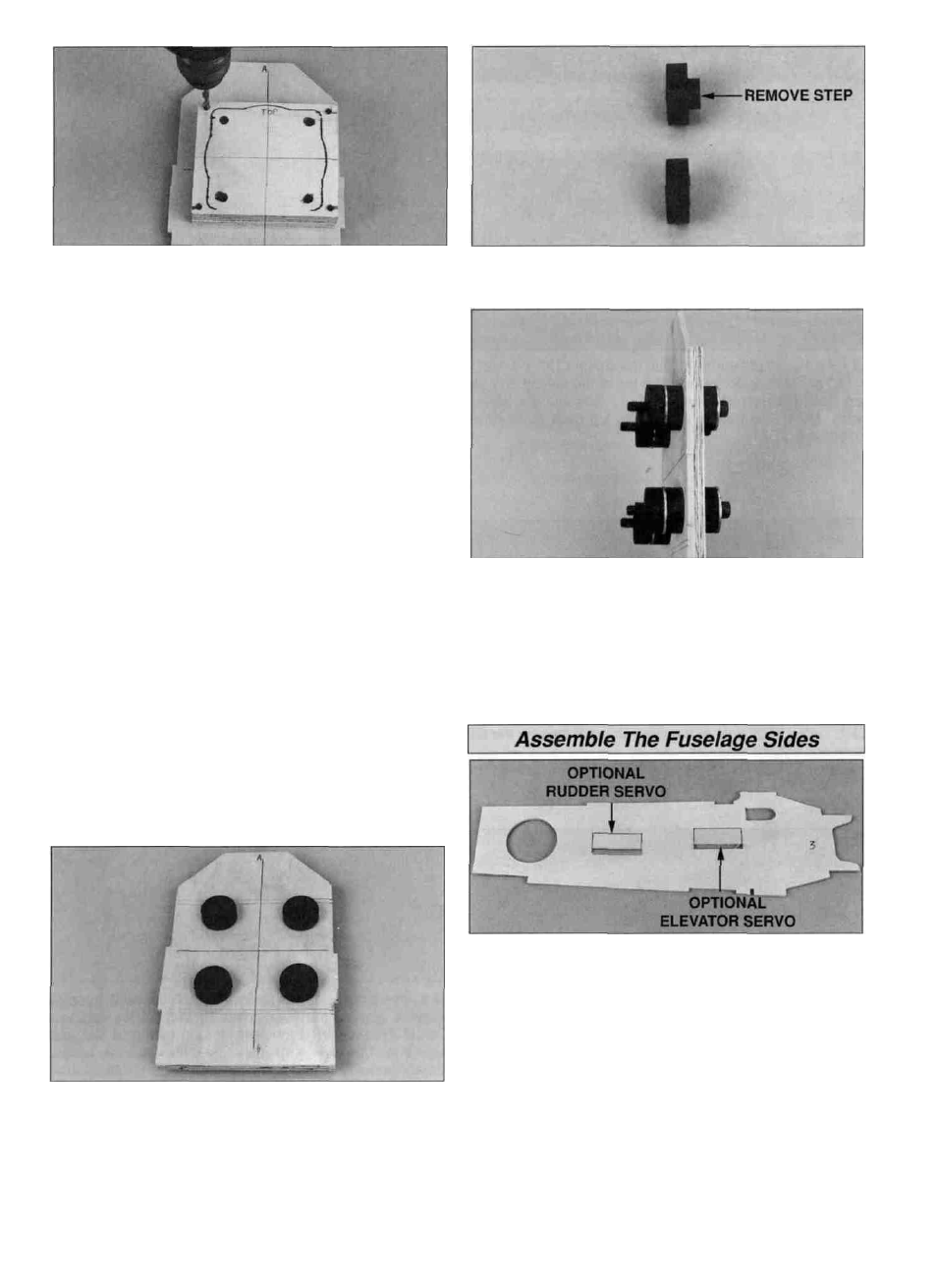
D 7. With the engine mounted on the engine spacer, trace
around the engine backplate. Mark the top of the engine
spacer (the edge opposite the engine head). Remove the
engine from the engine spacer. Clamp the engine spacer to
the firewall with the centerlines on the engine spacer
aligned with the centerlines on the firewall. Make sure the
top of the engine spacer is to the top of the firewall (the
angled end). Use a 3/16" drill bit to drill a hole in each
corner of the engine spacer, outside the engine outline,
through the engine spacer and firewall. Remove the engine
spacer and enlarge the holes in only the firewall with a 1/4"
drill bit.
D 8. Install 10-32 blind nuts (not included) in the back of
the firewall. Gently tap the blind nuts in with a hammer.
Apply a few drops of thin CA around each blind nut flange
to secure it.
D 12. Use a sharp hobby knife to carefully trim the step
from the four remaining rubber bushings.
D 9. Mount the engine to the engine spacer. Then mount
the engine spacer to the firewall with four 10-32 x 1-1/4"
socket head bolts and #10 washers (not included). Place a
mark on the firewall in line with the throttle arm. If not
installing an isolated engine mount, proceed to "Assemble
The Fuselage Sides."
D 13. Place a 1/4" washer on each of four 1/4-20 x 2"
socket head bolts. From the back of the firewall insert the
bolts through the rubber bushings. Install a 1/4" washer and
stepless bushing (from step 12,) on each 1/4-20 bolt.
Thread the bolts into the backplate of the engine and check
for fit. Place a mark on the firewall in line with the throttle
arm for the throttle pushrod exit. Remove the engine and
set it aside for now.
D 10. To install the J'TEC isolated engine mount, remove
the muffler and center the engine on the firewall using the
lines on the firewall as a guide. Mark the bolt hole locations
and drill a 1/2" hole at each mark.
D 11. Insert a rubber step bushing in the front and rear of
each hole. Note: The rubber bushings with attached blind
nuts are not used in this engine installation.
D 1. On the die-cut 1/8" ply fuselage side doubler #3
there are two embossed optional cut-outs for the rudder
and elevator servos. If you prefer to mount your servos in
the tail, punch out one of the cut-outs, for the rudder servo,
in one piece only and both cut-outs, for the elevator, in both
pieces. Use the punched out pieces glued to the back of
the doubler as doublers for the servo screws. If you prefer
to mount the servos in the standard location inside the
fuselage, punch out the narrow slots only. Glue the servo
cut-outs in place with thin CA. The slot in the fourth cut-out
may be used as an optional antenna exit.
26