Great Planes Giant Aeromaster Kit - GPMA0502 User Manual
Page 25
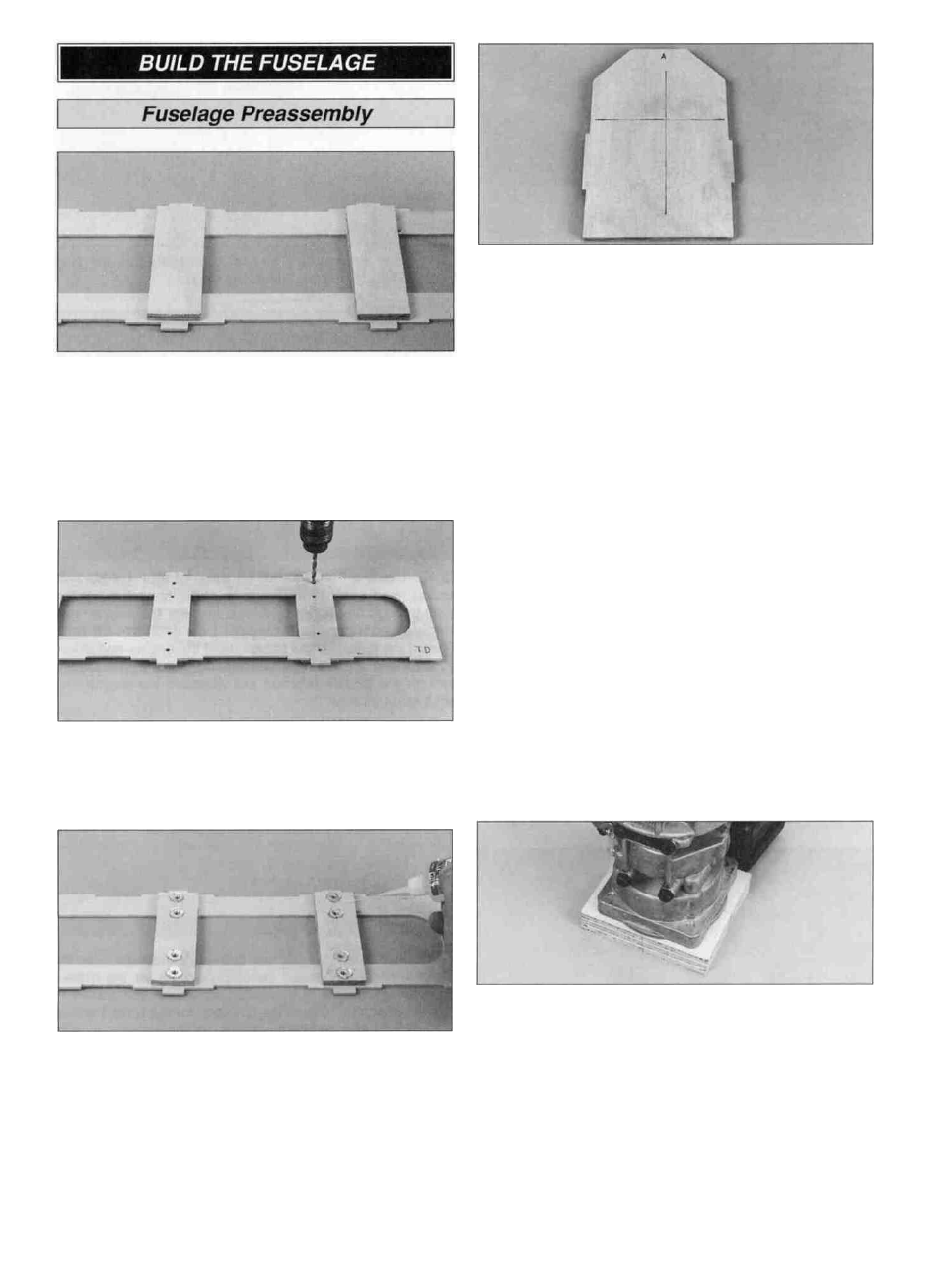
D 1. Use 6-minute epoxy to glue the shaped 1/4" x 1-1/2" x
4-1/2" ply cabane doublers to the top of the die-cut 1/8" ply
top deck (TD) centered between the tabs and the die-cut
holes. Note: The bottom side of the top deck features an
embossed (TD).
D 2. Drill a 5/32" hole at each punch mark through the top
deck and cabane doublers.
D 4. Draw centerlines connecting the punch marks on the
front of the die-cut 1/8" ply firewall (A). Use 30-minute
epoxy to glue firewall (A) to the shaped 1/4" ply firewall
doubler. Make sure the lines you previously drew are
facing forward and the bottom and edges of firewall (A)
and the firewall doubler are aligned. Wipe off the excess
epoxy before it cures.
Note: If firewall (A) and the firewall doubler are warped,
simply clamping them together may not "cancel out" the
warp. It is best to clamp the assembly to a table or a
flat board.
Important: We strongly recommend that any engine used
on the Giant Aeromaster be installed on an isolated shock
absorbing engine mount. The use of this type engine mount
will help prevent damage to the radio system and the
airplane frame due to engine vibration.
D 5. Skip ahead to step 10 if you will be installing the
recommended U.S. Engines 41cc engine and J'TEC
isolated engine mount on your Giant Aeromaster. If you are
not installing the isolated engine mount, use 30-minute
epoxy to laminate the three 1/4" x 3-1/4" x 3-3/4" ply
engine spacers together. If you will be installing a different
engine, center the engine on the firewall. The distance from
the firewall to the front of the drive washer needs to be
7-1/8" for the cowl to fit properly. Note: The following
instructions are based on the installation of the U.S.
Engines 41cc engine. Installation of your specific engine
may differ slightly.
D 3. Press a 6-32 blind nut into each hole. Use a 6-32 x
5/8" socket head bolt and #6 washer installed through the
cabanes to pull the blind nuts into the cabane. This will
ensure proper alignment of the cabanes and the blind nuts.
Add a few drops of thin CA around each blind nut flange to
secure them.
D 6. Use a ballpoint pen to draw centerlines on the engine
spacers. Extend the lines down the side of the spacers.
Center the engine on the spacers and mark the bolt hole
locations. The engine spacer is mounted with the shorter
dimension vertical. Drill and countersink a 1/4" hole at each
mark. Mount the engine to the spacer with 1/4-20 x 1-1/4"
flat head bolts (not included). During final assembly use
thread lock on the bolts to prevent loosening from vibration.
25