Great Planes Giant Aeromaster Kit - GPMA0502 User Manual
Page 36
D 6. Attach a solder clevis to the outermost hole in the
aileron servo arm. Center the aileron and the aileron servo
arm, then cut the aileron pushrod to the appropriate length.
Remove the aileron pushrod and the solder clevis from the
wing. Slide a silicone retainer on the pushrod then solder
the clevis on the end of the pushrod. Silver solder is highly
recommended. Reinstall the pushrod on the aileron servo
arm and the aileron control horn.
Some modelers prefer to install the pushrods and control
horns after the model is covered. If this is your preference
skip ahead to Assemble the Wheel Pants. Return to this
section after you have covered the model and joined the
control surfaces to the model with hinges.
D 7. Use a hobby knife to remove the area above the
bottom hole on two of the small control horns (as shown
in the drawing above). Use 2-56 x 5/8" screws and
backing plate to mount the control horn on the top TE of
the aileron and aligned with the slots for the strut tabs.
D 8. Repeat the process for the aileron in the other wing half.
D 9. If you are installing aileron servos in the top wing,
repeat the procedure for installing the aileron servos. If not,
use a hobby knife to trim two more of the small control
horns as before. Use 2-56 x 5/8" screws and backing plate
to mount the control horn at the TE of the aileron and
aligned with the slots for the strut tabs, on the top wing.
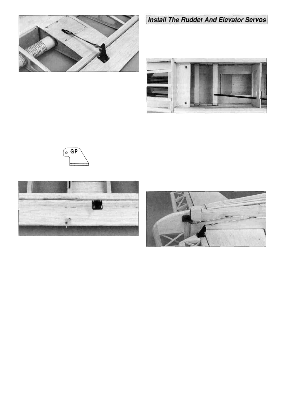
D 1. Cut the 1/4" x 1/2" x 10" basswood stick in half to
make the servo rails. Test fit the servo rails in the slots in
the fuselage doublers. Check that your servos will fit
between the rails. If not, slightly trim the slots in the
fuselage doubler. Use 6-minute epoxy to glue the servo
rails in the slots.
D 2. After the epoxy cures, cut the outer pushrod tubes so
that they are 1-1/2" back from the aft servo rail.
D 3. Thread three 4-40 nuts and metal clevises thirteen
complete turns onto three 4-40 x 36" threaded rods. Slide a
silicone clevis retainer over each clevis.
D 4. Attach a heavy duty control horn on each clevis. Insert
the pushrods into the rudder and elevator pushrod outer
tubes installed in the fuselage. Position the control horns on
the rudder and elevators so that the clevis holes are
aligned with the hinge joint. Mark the mounting holes and
drill 7/64" holes through the rudder and elevators, then
prick a few holes into the wood under the horn's location.
Apply a drop or two of thin CA to the pin holes to strengthen
the wood. When cured, attach the control horns with 4-40 x
1" machine screws and the backing plate.
D 5. Center the servo arms then position four servos on
the servo rails with the pushrods on the correct side of the
servos, as shown on the plans. Mark the servo mounting
holes and use servo mounting screws to attach the servos
to the servo rail. The servos for the rudder and elevator
must be high torque servos. The servo for the throttle can
be a standard servo.
36