Great Planes Giant Aeromaster Kit - GPMA0502 User Manual
Page 42
1 Start with the elevators and stab Cut the covering from
the hinge slots
2 If you are installing large plastic hinges, use 150-grit
sandpaper to scuff-up the hinge Carefully apply petroleum
jelly to the hinge pin area The petroleum jelly will prevent
epoxy from getting into the hinge pin area
3 Apply 30-minute epoxy to the hinges and inside the
hinge slots Install the hinges and close the hinge gap to
1/32" or less Wipe off any excess epoxy that squeezes out
of the hinge slots with a cloth dampened with alcohol
4 After the epoxy has cured flex the hinged surfaces to
loosen any epoxy in the hinge pin area
5 Repeat the hinge gluing process for the rudder and
ailerons
6 If you have not yet installed and connected the control
horns and elevator, rudder and aileron pushrods return to
"Install The Rudder And Elevator Servos" on page 36 for
instructions
D 1 Assemble the fuel tank per the manufacturers
instructions Place 1/4" foam padding on the tank floor,
fuselage sides and the bottom of the top deck Insert two 1'
pieces of fuel tubing through the firewall from the engine
side Connect one of the fuel tubes to the fuel pick-up fitting
and the other to the overflow fitting on the tank Slide the
tank through the opening above former (C) as you carefully
pull the fuel lines through the firewall
D 2 Use 6-minute epoxy to glue the tail wheel wire in the
rudder Before the epoxy cures screw the tail wheel bracket
to the bottom of the fuselage.
D 3. Install a 1/8" wheel collar on the tail wheel wire
followed by a 1-1/2" tail wheel. Secure the tailwheel with a
second 1/8" wheel collar
D 4 Apply masking tape to the wheel pants and install
wheels Mount the wheel pants to the landing gear Secure
the axle nuts with a drop of threadlock.
D 5. Mount the landing gear to the fuselage with
6-32 x 5/8" socket head bolts and #6 flat washers. Be sure
to use thread lock on the threads of the bolt
D 6 Wrap the receiver and battery pack in 1/4" or thicker
foam rubber Install one each in the two recesses between
formers (K), (L) and the instrument panel Pack extra foam
in the compartments to keep the receiver and battery pack
from dislodging during aerobatics or rough landings Glue a
mixing stick over each recess for added security.
D 7 Mount the receiver switch in a convenient location Be
sure that will not interfere with the servos and pushrods
inside the fuselage
D 8. Switch the radio system on and center the servo
arms Install the elevator and rudder pushrods first, then
install and hook up the control horns
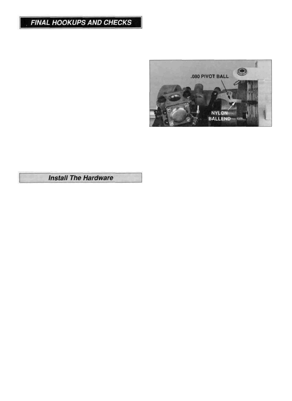
D 9 If you are using the included throttle pushrod, secure
a .080" pivot ball to the engine throttle arm with a .080"
nut Apply threadlock to the nut to prevent it from vibrating
loose Thread the nylon ball end 13 turns onto the 2-56 x
36" threaded rod Install a Screw-Lock Pushrod
Connector on the throttle servo arm Insert the throttle
pushrod in the throttle tube and through the pushrod
connector Snap the nylon ball end onto the pivot ball With
the radio system switched on adjust the throttle so that the
carburetor opens completely at full throttle and closes
completely when the throttle stick is moved to idle and the
trim is reduced Use threadlock on the 1/8" socket head
cap screw in the pushrod connector Cut off the excess
throttle pushrod
D 10 If you installed an optional antenna tube in the
fuselage, route the receiver antenna through the tube and
out the aft end of the fuselage If you did not install the
antenna tube drill a small hole in the aft wing mounting
plate Make a strain relief from a cut off servo arm and
place it on the antenna near the receiver Route the
antenna through the hole in the mounting plate and down
the bottom of the fuselage You can make a hook out of
another cut-off servo arm and loop the end of the antenna
to it, then connect the other end of the cut-off servo arm to
a rubber band looped around the tailwheel wire - or you
can also use a piece of trim sheet and tape the antenna to
the bottom of the fuselage.
D 11 Apply 1/16" foam seating tape on the wing saddle of
the fuselage (optional)
D 12 Prepare the engine compartment for cowl installation
by connecting the fuel pick-up line to the carburetor routing
the overflow line out the bottom of the fuselage and
installing the fuel fill valve Install the cowl then the
propeller
D 13 Use 6-32 x 5/8" socket head bolts and #6 washers
to attach the cabane struts to the fuselage Make sure to
use thread lock on all the bolts.
42