Phase, Blend (s+h - osc - noise) and pink, Ring mod – FXpansion DCAM Synth Squad Operation Manual User Manual
Page 21: Gain, Filter mix, 3 shaper section, Power button, Post button, Mode, Drive
1
Phase
Each osc’s phase can be set with the
Phase parameter.
With the
Rset (Reset) button enabled, the phase is reset to the value defined by the Phase parameter on each envelope
retrigger event (which is dependent on the Retrig button).
Disabling the Reset button means that the phase is effectively free-running.
The Phase control can be continuously modulated in real time for phase modulation effects (at control-rate rather than
audio-rate).
Low
The
Low button on each osc switches it to act as an LFO, with the Beat parameter controlling its rate in Hz. Each osc is
available as a control-rate TransMod source for use with this function (see section 7:8).
Key
The
Key button turns keytracking (modulation of pitch by the keyboard) on or off for each osc.
Blend (S+H - Osc - Noise) & Pink
The
Blend control crossfades the final audio output from each oscillator between the oscillator itself (centre position),
white/pink noise (fully right), and another osc sampled and held at audio-rate by the osc’s frequency (fully left).
Section 4:4 offers a detailed analysis of the audio-rate sample and hold feature.
When the
Pink button is engaged, the noise source outputs pink noise. When the button is deactivated, the source is set
to white noise.
Note that when using the CypherFX plugin (MIDI-controlled audio effect plugin version), external audio appears in place
of the white noise source in each osc – the Pink noise source is still available for each osc. Therefore, to hear the external
audio source, you must disable the Pink button.
Ring mod
Each oscillator features a ring modulation function, allowing it to be multiplied by one of the other oscillators. Enabling the
Ring Mod button for an osc results in the sum and difference of the oscs’ frequencies being used as the output of the osc.
If the oscs’ frequencies are harmonically related, the result is a musical sound; if not, the output may be dissonant. The
ring modulation process occurs after the
Blend control in the signal path.
Osc1: Osc2 x Osc1
Osc2: Osc3 x Osc2
Osc3: Osc1 x Osc3
Gain
The
Gain control sets the final output level of each oscillator. At a setting of zero, the osc is not heard in the final output.
However, its effect is still heard if it is modulating one of the other oscs.
Filter Mix
Each Osc’s
Filter Mix control determines the amount of signal from the osc that is routed to each of the two filter/shaper
paths. When at the centre position, the osc’s signal is sent equally to both filter/shaper paths.
3:3 Shaper section
Each of Cypher’s two filter paths features a polyphonic waveshaping block that can be placed before or after the filter.
A waveshaper applies a mathematical function to the incoming waveform in order to alter its harmonic content and
introduce distortion. It is useful for overdriving the signal to add abrasive grit and character.
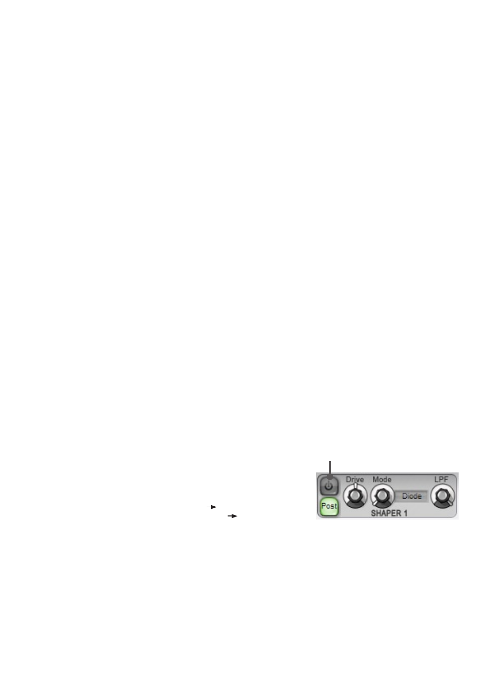
Shaper Power
Power
To enable each of the waveshaper blocks, engage its
Power button.
Post
With its
Post button turned off, the waveshaper block is placed before the
corresponding filter block (for example, shaper 1
filter 1). By engaging the
Post button, the shaper is moved after the filter (filter 1
shaper 1).
Mode
This control selects from 4 distinct waveshaper models, each providing its own distortion flavour. ‘Diode’, ‘OTA’ (operational
transconductance amplifier), ‘OpAmp’ (operational amplifier) and ‘HalfRect’ (half-rectifier) shapers are available. Graphical
plots of these shaper modes are provided in Appendix 3.
Drive
The
Drive control increases the gain of the signal going into the waveshaper – higher values drive the waveshaper harder,
leading to more grit and distortion.
LPF
The
LPF control applies a 1-pole Low-pass filter after the waveshaper for dialling out high frequencies and harmonics as
required.