3 filter section, Filter controls, Power – FXpansion DCAM Synth Squad Operation Manual User Manual
Page 15: Cutoff and res (resonance), Drive, Mode, Direct modulation, Filter section
15
2:3 Filter section
Filter cutoff
direct mod: Key
Filter cutoff
direct mod: LFO
Filter cutoff
direct mod: Env
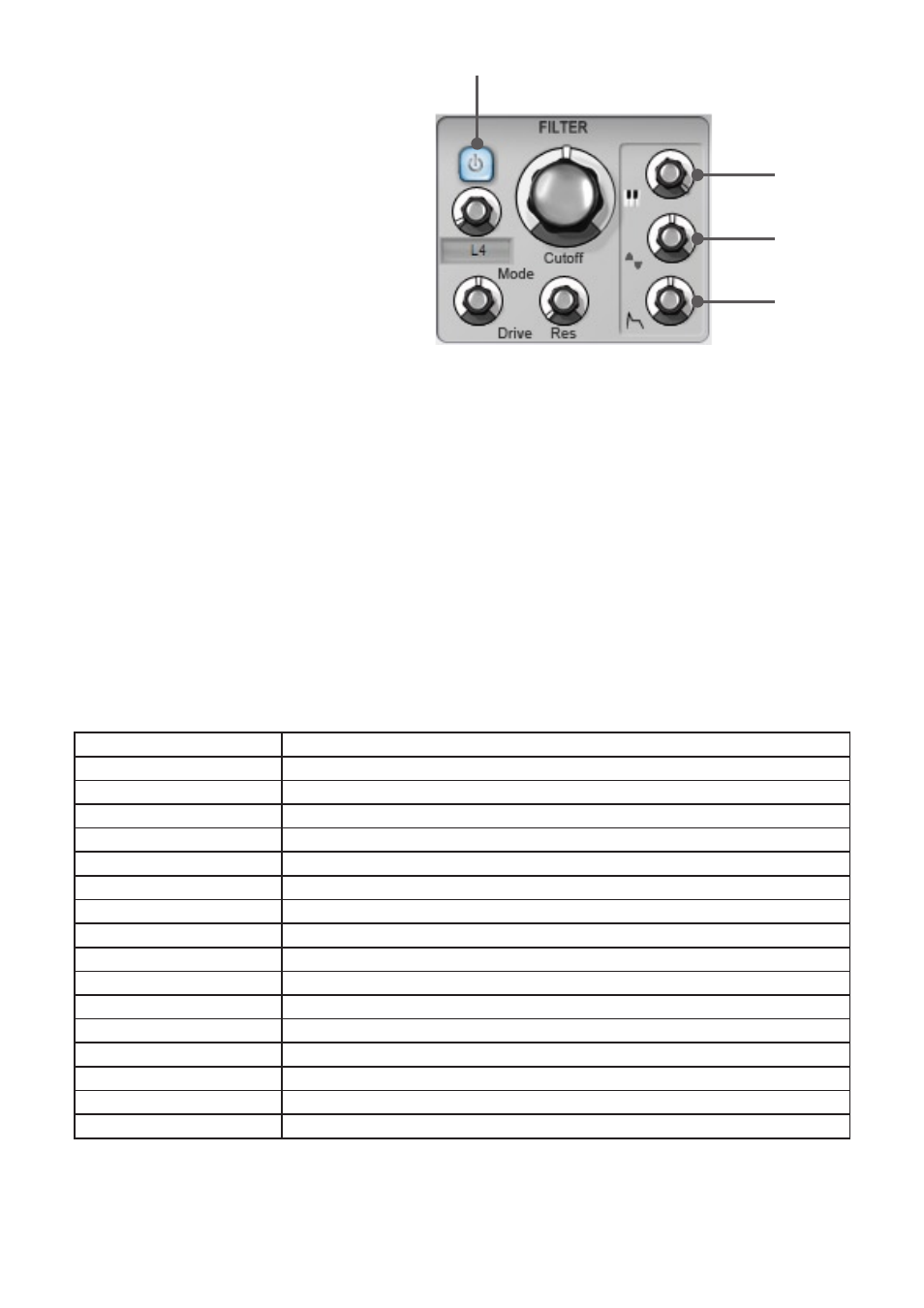
Filter Power
Strobe’s filter is its main source of tonal variation,
especially when modulated. While there are direct
modulation routings to the cutoff from the keyboard
pitch, LFO and Mod Envelope, the filter’s controls
can be modulated with the TransMod system for
really creative and varied effects.
Strobe’s filter is based on an OTA (operation
transconductance amplifier) cascaded core, with a
diode clipper in the feedback section. The diodes
are slightly mismatched, leading to the characteristic
growl of a real analog filter.
Filter controls
Power
The
Power button switches the filter on or off. When
the button is disabled, the audio from the oscillator passes through the filter unaffected.
Cutoff & Res (Resonance)
The
Cutoff control determines the cutoff frequency of Strobe’s filter.
The
Res control adds emphasis around the cutoff frequency, giving a warm, resonant sound to the osc tone. At extreme
Res settings, the filter self-oscillates.
The cutoff can be modulated from the keyboard, LFO and Mod Envelope using the dedicated controls.
The control is adjusted in semitones, allowing you to tune the self-oscillating filter just like an oscillator. Setting the
keytracking depth control to maximum allows you to ‘play’ the filter musically from the keyboard.
Drive
The
Drive control increases the gain of the signal going into the filter. This overloads the filter’s components, drastically
changing its sound and character.
Note that the effective resonance is reduced as you turn up the Drive control.
Mode
A large variety of filter modes are available by adjusting the
Mode control.
Note that filters denoted as ‘T’ feature 2 or more filters with an octave between the frequency of each. The first filter in the
name is at the cutoff frequency, with subsequent filters each an octave higher than the last. The only exceptions are the
last 2 filter modes - see the table below. Graphical plots of the filter responses can be found in Appendix 2.
In other combination filters, all filters act at the cutoff frequency.
L2, L4, B2, B4, H2, H4
2-pole (12 dB/oct.) & 4-pole (24 dB/oct.) Low-pass, Band-pass & High-pass filters
P2
2-pole Peak filter
NP2
1-pole Notch and 2-pole Peak filters
N2P2 T
2-pole Notch and 2-pole Peak filters, an octave apart
N2L2 T
2-pole Notch and 2-pole Low-pass filters, an octave apart
N2H1L1 T
2-pole Notch, 1-pole High-pass and 1-pole Low-pass filters, each an octave apart
P2N2 T
2-pole Peak and 2-pole Notch filters, an octave apart
H2N2 T
2-pole High-pass and 2-pole Notch filters, an octave apart
H1L1N2 T
1-pole High-pass, 1-pole Low-pass and 2-pole Notch filters, each an octave apart
N2P2N2 T
2-pole Notch, 2-pole Peak and 2-pole Notch filters, each an octave apart
N2
2-pole notch filter
N4
4-pole notch filter
N2L2
2-pole Notch and 2-pole Low-pass filters
H2N2
2-pole High-pass and 2-pole Notch filters
H1N2L1
1-pole High-pass, 2-pole Notch and 1-pole Low-pass, each an octave apart
N2N2A T
2-pole Notch with 2-pole Notch an octave higher than the cutoff frequency
N2N2B T
2-pole Notch with 2-pole Notch an octave lower than the cutoff frequency
Direct modulation
The filter section contains dedicated controls for setting modulation depth of the filter
Cutoff by 3 modulation sources:
• Keytracking
• LFO
• Mod Envelope