Expansion connectors and boards, Expansion connectors, Chapter 13: expansion connectors and boards – Digilent 410-044-10P-KIT User Manual
Page 47: Chapter 13, “expansion connectors and boards, Chapter 13
Spartan-3 Starter Kit Board User Guide
47
UG130 (v1.1) May 13, 2005
1-800-255-7778
R
Chapter 13
Expansion Connectors and Boards
Expansion Connectors
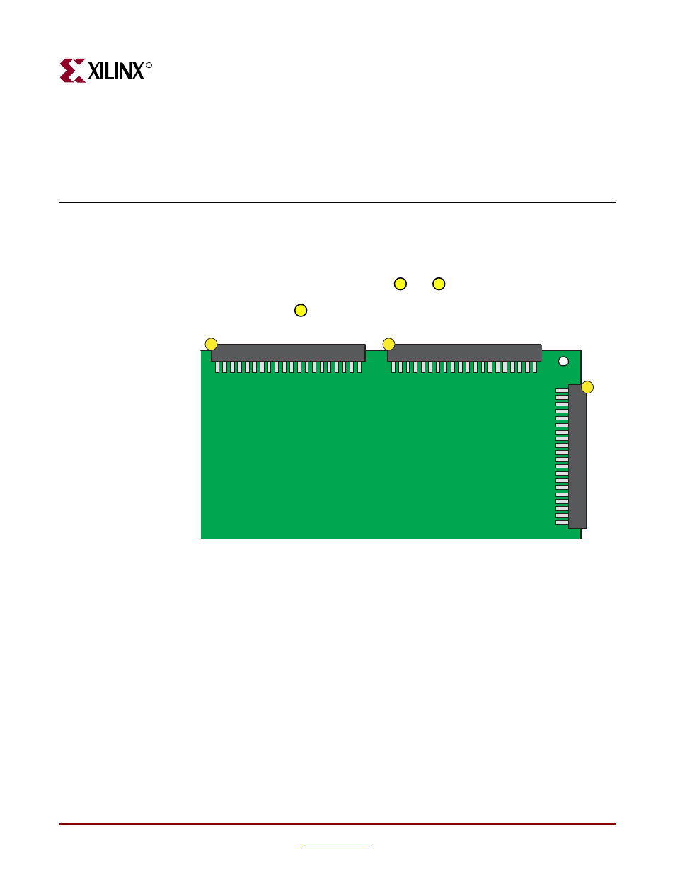
The Spartan-3 Starter Kit board has three 40-pin expansion connectors labeled A1, A2, and
B1. The A1 and A2 connectors, indicated as
and
, respectively, in
, are on
the top edge of the board. Connector A1 is on the top left, and A2 is on the top right. The B1
connector, indicated as
in
, is along the right edge of the board.
summarizes the capabilities of each expansion port. Port A1 supports a
maximum of 32 user I/O pins, while the other ports provide up to 34 user I/O pins. Some
pins are shared with other functions on the board, which may reduce the effective I/O
count for specific applications. For example, pins on the A1 port are shared with the SRAM
address signals, with the SRAM OE# and WE# control signals, and with the eight least-
significant data signals to SRAM IC10 only.
Figure 13-1:
Spartan-3 Starter Kit Board Expansion Connectors
21
20
19
A2 Expansion Connector
A1 Expansion Connector
B1 Expansion Connector
21
20
19
UG130_c12_01_042704