Table 3-1, Table 3-2, Table 3-3 – Digilent 410-044-10P-KIT User Manual
Page 17
Spartan-3 Starter Kit Board User Guide
17
UG130 (v1.1) May 13, 2005
1-800-255-7778
R
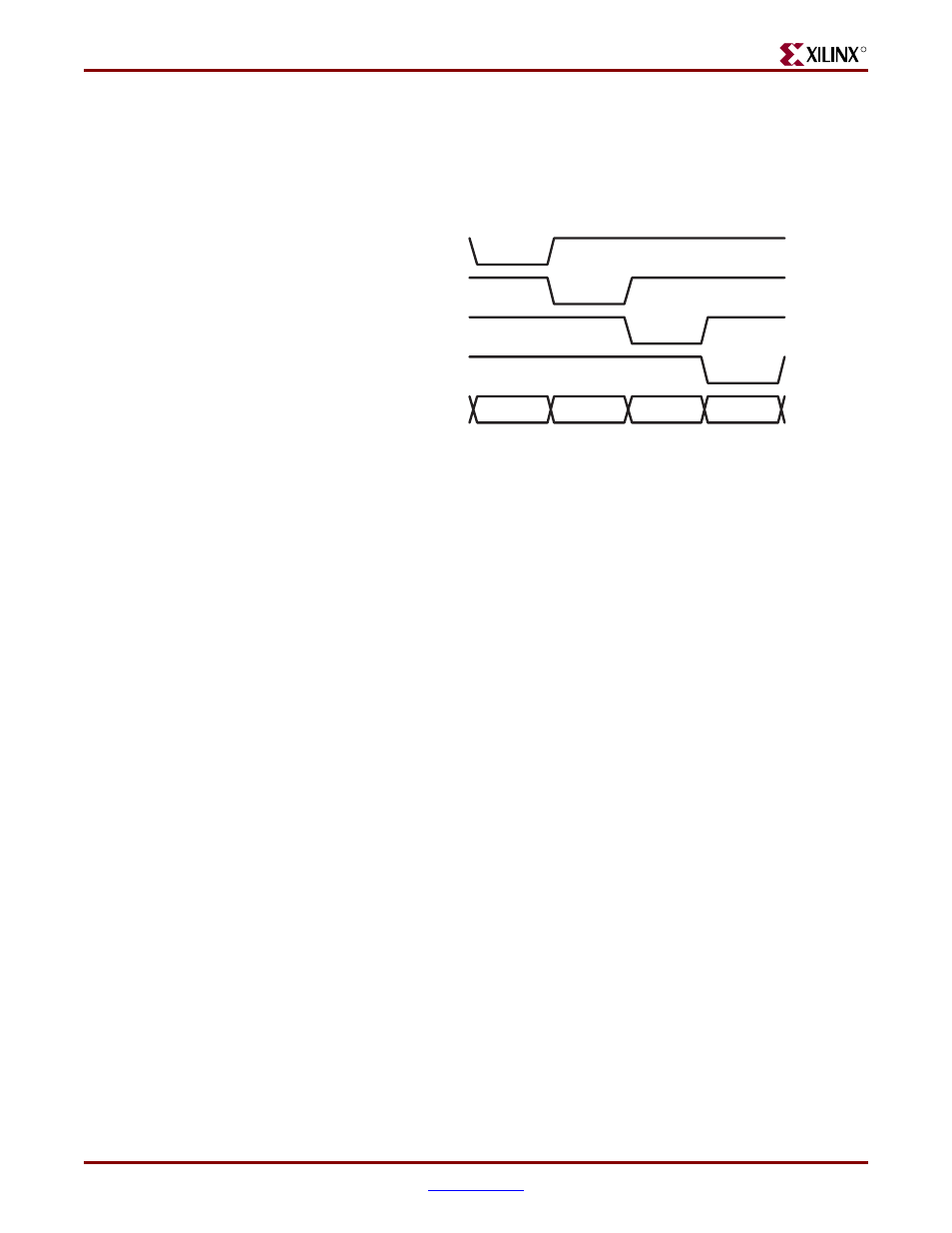
The LED control signals are time-multiplexed to display data on all four characters, as
shown in
Figure 3-2
. Present the value to be displayed on the segment control inputs and
select the specified character by driving the associated anode control signal Low. Through
persistence of vision, the human brain perceives that all four characters appear
simultaneously, similar to the way the brain perceives a TV display.
This “scanning” technique reduces the number of I/O pins required for the four
characters. If an FPGA pin were dedicated for each individual segment, then 32 pins are
required to drive four 7-segment LED characters. The scanning technique reduces the
required I/O down to 12 pins. The drawback to this approach is that the FPGA logic must
continuously scan data out to the displays—a small price to save 20 additional I/O pins.
Figure 3-2:
Drive Anode Input Low to Light an Individual Character
AN3
AN2
AN1
AN0
DISP3
DISP2
DISP1
DISP0
{A,B,C,D,E,F,G,DP}
UG130_c3_02_042404