Figure 11-2 – Digilent 410-044-10P-KIT User Manual
Page 42
42
Spartan-3 Starter Kit Board User Guide
1-800-255-7778
UG130 (v1.1) May 13, 2005
Chapter 11: JTAG Programming/Debugging Ports
R
The J7 header also supports the Xilinx Parallel Cable 3 (PC3) download/debugging cable
when using the flying leaders. Again, make sure that the signals at the end of the JTAG
cable align with the labels listed on the board.
provides a detailed schematic of the J7 header and the JTAG programming
chain.
Parallel Cable IV/MultiPro Desktop Tool JTAG Header (J5)
The J5 header, shown as
, supports the Xilinx download/debugging
cables listed below:
•
MultiPro Desktop Tool
•
Parallel Cable IV (PC IV)
Use the 14-pin ribbon cable supplied with both cables to connect to the J5 header. DO NOT
use the flying leads that are also provided with some cables. Although the MultiPro
Desktop Tool and the Parallel Cable IV support multiple FPGA configuration modes, the
Spartan-3 Starter Kit board only supports the JTAG configuration method. The header is
designed for a keyed socket. However, the Spartan-3 Starter Kit uses only stake pins. The
outline of the keyed connector appears around the J5 header, as shown in
When properly inserted, the keyed header matches the outline on the board and the ribbon
cable crosses over the top edge of the board. The red-colored lead indicates pin 1 on the
cable and should be on the left side.
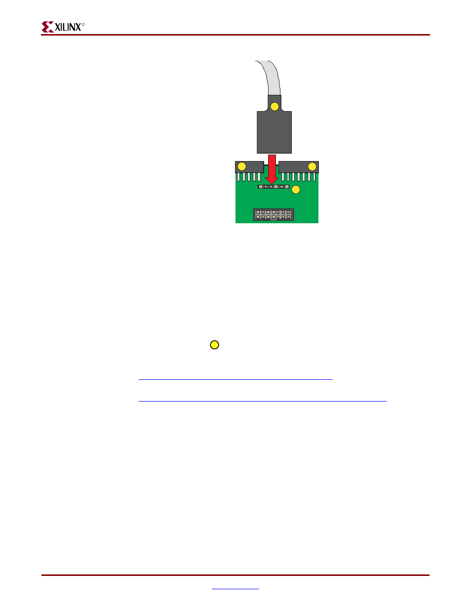
Figure 11-2:
Digilent JTAG Cable Provided with Kit Connects to the J7 Header
TMS
TDI
TDO
TCK
GND
VDD
2.8V
UP T
O
5V
J7
UG130_c11_02_042704
23
21
20
22
TMS
TDI
TDO
TCK
GND
VCC
24