Program push button/done indicator led, Vg a – Digilent 410-044-10P-KIT User Manual
Page 37
Spartan-3 Starter Kit Board User Guide
37
UG130 (v1.1) May 13, 2005
1-800-255-7778
Program Push Button/DONE Indicator LED
R
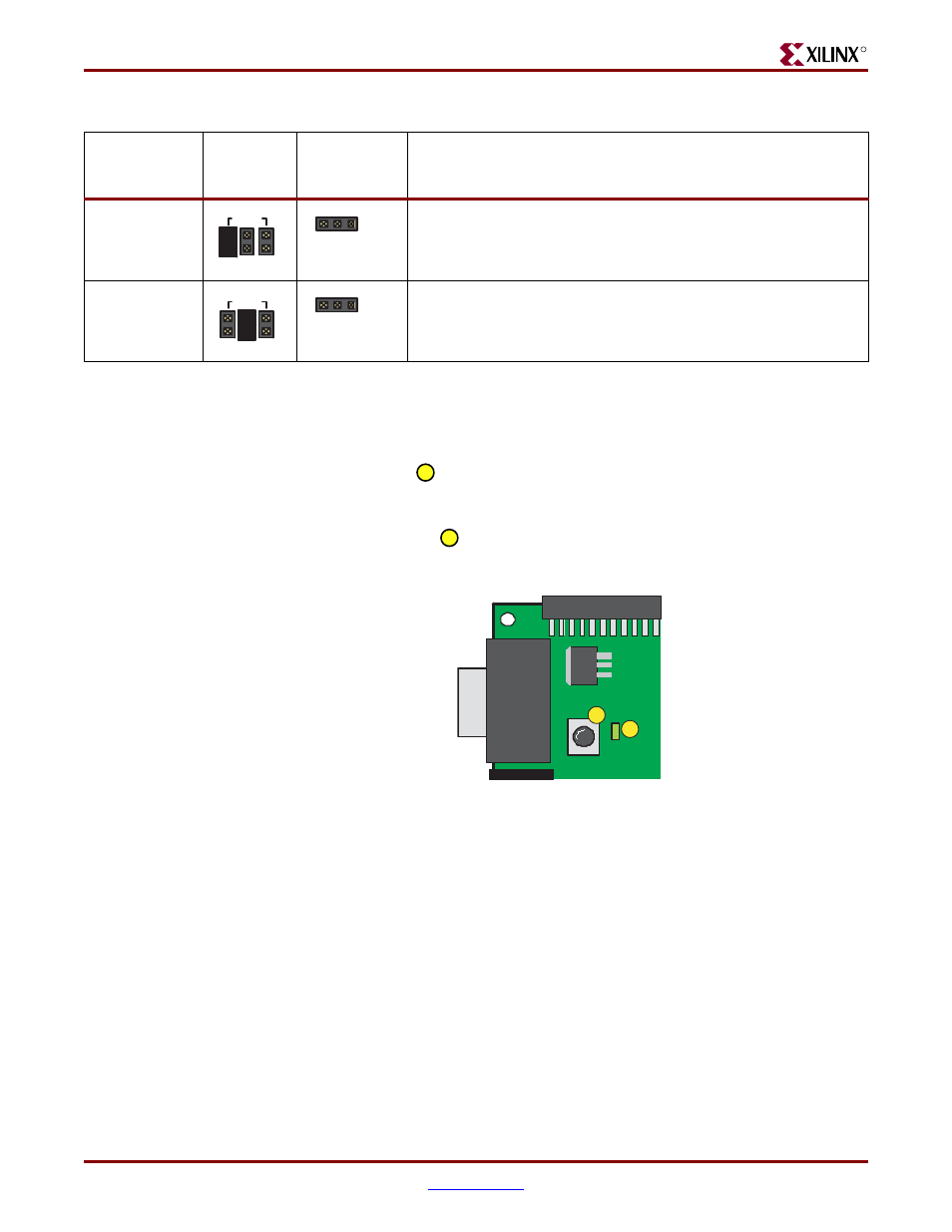
Program Push Button/DONE Indicator LED
The Spartan-3 Starter Kit Board includes two FPGA configuration functions, located near
the VGA connector and the AC power input connector, as shown in
Figure 9-1
. The PROG
push button, shown as
in
Figure 9-1
, drives the FPGA’s PROG_B programming pin.
When pressed, the PROG push button forces the FPGA to reconfigure and reload it
configuration data.
The DONE LED, shown as
in
Figure 9-1
, connects to the FPGA’s DONE pin and lights
up when the FPGA is successfully configured.
Slave Parallel
<0:1:1>
Another device connected to the B1 expansion connector
provides parallel data and clock to load the FPGA.
JTAG
<1:0:1>
The FPGA waits for configuration via the four-wire JTAG
interface.
Table 9-1:
Header J8 Controls the FPGA Configuration Mode
(Continued)
Configuration
Mode
Header J8
Settings
Jumper JP1
Setting
Description
MODE
M0 M1 M2
J8
GND
JP1
MODE
M0 M1 M2
J8
GND
JP1
Figure 9-1:
The PROG Button and the DONE LED
17
18
PROG
DONE
VG
A
VGA
UG130_c9_03_042704
17
18