Signal timing for a 60hz, 640x480 vga display – Digilent 410-044-10P-KIT User Manual
Page 22
22
Spartan-3 Starter Kit Board User Guide
1-800-255-7778
UG130 (v1.1) May 13, 2005
Chapter 5: VGA Port
R
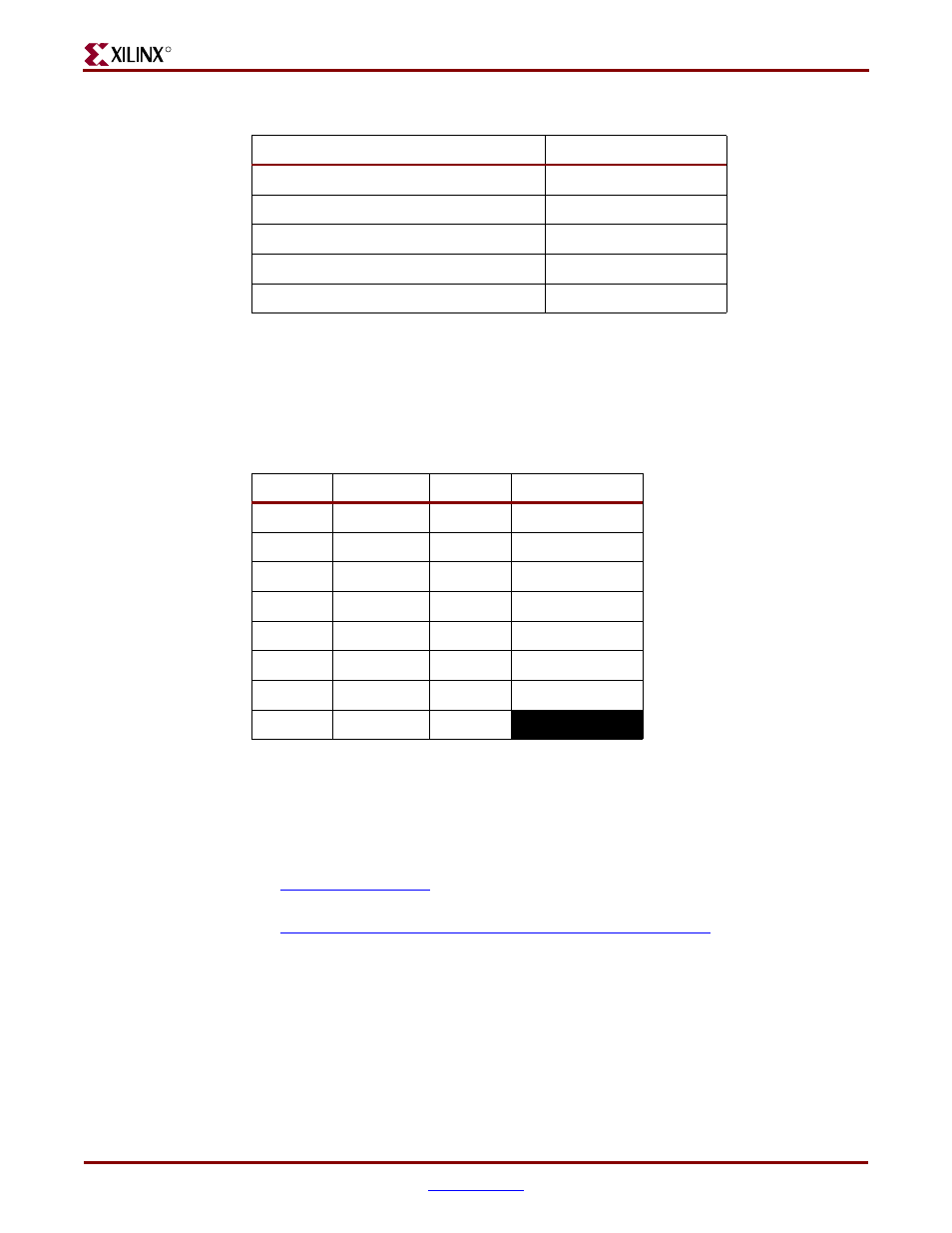
Each color line has a series resistor to provide 3-bit color, with one bit each for Red, Green,
and Blue. The series resistor uses the 75
Ω VGA cable termination to ensure that the color
signals remain in the VGA-specified 0V to 0.7V range. The HS and VS signals are TTL level.
Drive the R, G, and B signals High or Low to generate the eight possible colors shown in
Table 5-2
.
VGA signal timing is specified, published, copyrighted, and sold by the Video Electronics
Standards Association (VESA). The following VGA system and timing information is
provided as an example of how the FPGA might drive VGA monitor in 640 by 480 mode.
For more precise information or for information on higher VGA frequencies, refer to
documents available on the VESA website or other electronics websites:
•
Video Electronics Standards Association
•
VGA Timing Information
Signal Timing for a 60Hz, 640x480 VGA Display
CRT-based VGA displays use amplitude-modulated, moving electron beams (or cathode
rays) to display information on a phosphor-coated screen. LCD displays use an array of
switches that can impose a voltage across a small amount of liquid crystal, thereby
changing light permitivity through the crystal on a pixel-by-pixel basis. Although the
following description is limited to CRT displays, LCD displays have evolved to use the
Table 5-1:
VGA Port Connections to the Spartan-3 FPGA
Signal
FPGA Pin
Red (R)
R12
Green (G)
T12
Blue (B)
R11
Horizontal Sync (HS)
R9
Vertical Sync (VS)
T10
Table 5-2:
3-Bit Display Color Codes
Red (R)
Green (G)
Blue (B)
Resulting Color
0
0
0
Black
0
0
1
Blue
0
1
0
Green
0
1
1
Cyan
1
0
0
Red
1
0
1
Magenta
1
1
0
Yellow
1
1
1
White