Fpga configuration modes and functions, Fpga configuration mode settings, Chapter 9: fpga configuration modes and functions – Digilent 410-044-10P-KIT User Manual
Page 36: Chapter 9, “fpga configuration modes and functions, Chapter 9
36
Spartan-3 Starter Kit Board User Guide
1-800-255-7778
UG130 (v1.1) May 13, 2005
Chapter 9: FPGA Configuration Modes and Functions
R
Chapter 9
FPGA Configuration Modes and
Functions
FPGA Configuration Mode Settings
In most applications for the Spartan-3 Starter Kit Board, the FPGA automatically boots
from the on-board Platform Flash memory whenever power is applied or the PROG push
button is pressed. However, the board supports all the available configuration modes via
the J8 header, indicated as
.
Table 9-1
provides the available option
settings for the J8 header. Additionally, the JP1 jumper setting is required when using
Master Serial configuration mode, as further described in
“Platform Flash Jumper Options
The default jumper settings for the board are:
•
All jumpers in the J8 header are installed
•
The JP1 jumper is in the “Default” position
16
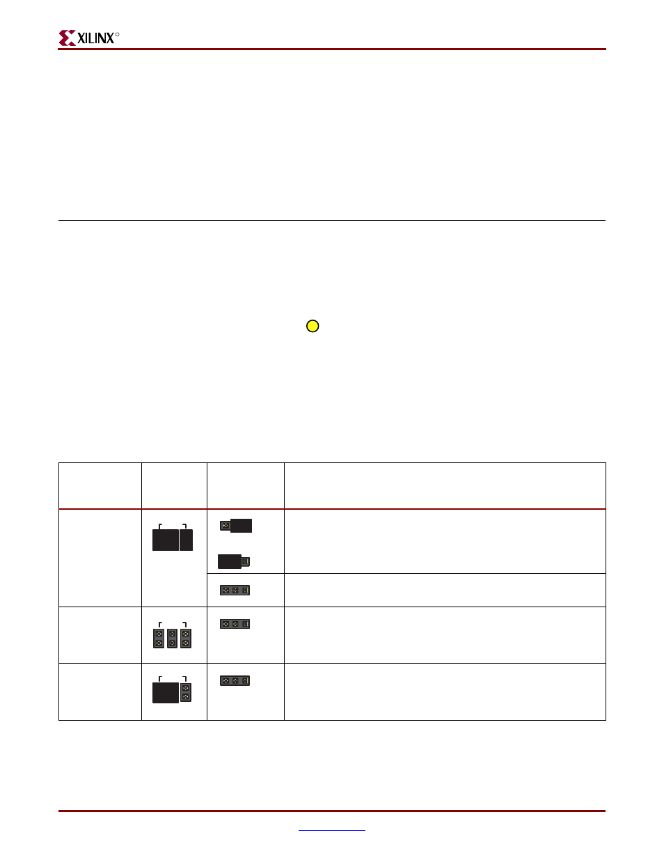
Table 9-1:
Header J8 Controls the FPGA Configuration Mode
Configuration
Mode
Header J8
Settings
Jumper JP1
Setting
Description
Master Serial
<0:0:0>
or
DEFAULT
. The FPGA automatically boots from the Platform
Flash.
The FPGA attempts to boot from a serial configuration source
attached to either expansion connector A2 or B1.
Slave Serial
<1:1:1>
Another device connected to either the A2 or B1 expansion
connector provides serial data and clock to load the FPGA.
Master Parallel
<1:1:0>
The FPGA attempts to boot from a parallel configuration source
attached to the B1 expansion connector.
M0 M1 M2
J8
GND
MODE
JP1
JP1
JP1
M0 M1 M2
MODE
J8
GND
JP1
MODE
M0 M1 M2
J8
GND
JP1