Digilent DIO2 User Manual
Page 7
Digilab DIO2 Reference Manual
Digilent, Inc.
www.digilentinc.com
page 7 of 19
Copyright Digilent, Inc. All rights reserved. Other product and company names mentioned may be trademarks of their respective owners.
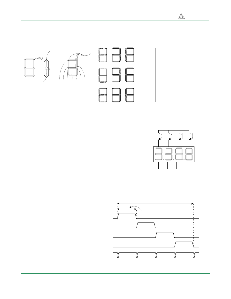
similar segments on all four displays are also connected together into seven common circuit nodes
labeled CA through CG. Thus, each cathode for all four displays can be turned on and off
independently.
Figure 4. (a) Seven segment display detail.
(b) common anode display configuration. (c)
segement illumination patterns for decimal.
digits. (d) segment illumination truth table.
Common anode
Digit
Illuminated Segment
Shown
a b c d e f g
0
1 1 1 1 1 1 0
1
0 1 1 0 0 0 0
2
1 1 0 1 1 0 1
3
1 1 1 1 0 0 1
4
0 1 1 0 0 1 1
5
1 0 1 1 0 1 1
6
1 0 1 1 1 1 1
7
1 1 1 0 0 0 0
8
1 1 1 1 1 1 1
9
1 1 1 1 0 1 1
a
f
e
d
c
b
g
a f g e d c b
(a)
(b)
(c)
(d)
This connection scheme creates a multiplexed display, where a 4-
digit display can be created by driving the anode signals and
corresponding cathode patterns of each digit in a repeating,
continuous succession. In order for each of the four digits to appear
bright and continuously illuminated, all four digits should be driven
once every 1 to 16ms (for a refresh frequency of 60Hz to 1KHz).
For example, in a 60Hz refresh scheme, each digit would be
illuminated for ¼ of the refresh cycle, or 4ms. The controller must
assure that the correct cathode pattern is present when the
corresponding anode signal is driven. To illustrate the process, if
AN1 is driven high while CB and CC are driven low, then a “1”
will be displayed in digit position 2. Then, if AN2 is driven high
while CA, CB and CC are driven low, then a “7” will be displayed
in digit position 2. If AN1/CB, CC are driven for 4ms, and then
AN2/CA, CB, CC are driven for 4ms in an endless succession, the
display will show “17” in the first
two digits. An example timing
diagram is provided below.
When configured with the code
shown in the appendix, the CPLD
on the DIO2 board implements a
seven-segment controller provided
a suitable clock (256Hx to 1KHz)
is provided on the CLK_IN pin.
The controller accepts four 4-bit
binary numbers in two successive
registers (at addresses 6 and 7), and
decodes and displays them.
a1
Cathodes -- connected to
CPLD pins via 100
Ω resistor
Anodes -- connected to CPLD
via transistors for greater current
Vdd
a b c d e f g dp
a2
a3
a4
AN1
AN2
AN3
AN4
Cathodes
Digit 1
Digit 2
Digit 3
Digit 4
Refresh period = 1ms to 16ms
Digit period = Refresh / 4
Seven segment display refresh signals and timings