Digilent DIO2 User Manual
Page 11
Digilab DIO2 Reference Manual
Digilent, Inc.
www.digilentinc.com
page 11 of 19
Copyright Digilent, Inc. All rights reserved. Other product and company names mentioned may be trademarks of their respective owners.
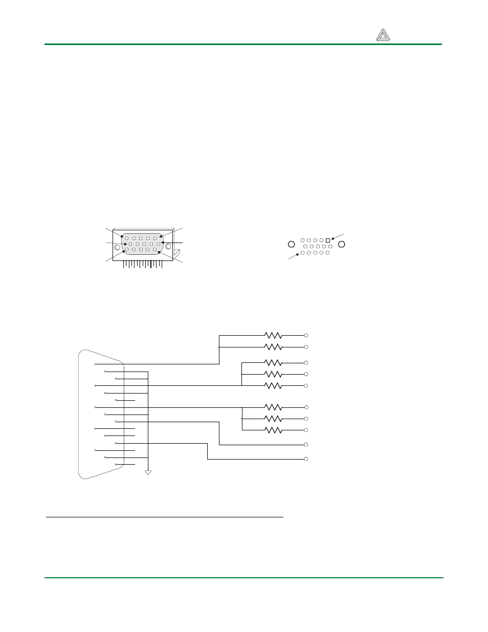
VGA port
The five standard VGA signals Red (R), Green (G), Blue (B), Horizontal Sync (HS), and Vertical Sync
(VS) are routed directly from the B connector to the VGA connector, bypassing the CPLD. A resistor-
divider network is used to provide 8-bit color, with 3 bits for blue, 3 bits for green, and 2 bits for red
(the human eye is less sensitive to red, so red got 2 bits instead of 3). The resistor network uses the 75
ohm VGA cable termination to ensure that the color signals remain in the VGA-specified 0V – 0.7V
range. The HS and VS signals are TTL level, and come directly from the FPGA via the B connector.
VGA signal timings are specified, published, copyrighted and sold by the VESA organization
(www.vesa.org). The following VGA system and timing information is provided as an example of how
a VGA monitor might be driven in 640 by 480 mode. For more precise information, or for information
on higher VGA frequencies, refer to document available at the VESA website (or experiment!).
VGA systems and signal timings for a 60Hz, 640x480 display
CRT-based VGA displays use amplitude modulated, moving electron beams (or cathode rays) to
display information on a phosphor-coated screen. LCD displays use an array of switches that can
impose a voltage across a small amount of liquid crystal, thereby changing light permitivity through
the crystal on a pixel-by-pixel basis. Although the following description is limited to CRT displays,
DB15 VGA connector
Front view
Pin 1
Pin 6
Pin 11
Pin 5
Pin 10
Pin 15
Pin 1
Pin 15
DB15 through-hole pattern as
seen from the top
1
6
11
2
7
12
3
8
13
4
9
14
5
10
15
GND
DB15
Connector
To R0 on Connector B
2K
Red
Green
Blue
Horizontal Sync
Vertical Sync
To R1 on Connector B
To G0 on Connector B
To G1 on Connector B
To G2 on Connector B
To B0 on Connector B
To B1 on Connector B
To B2 on Connector B
1K
512
2K
1K
512
1K
512
To HS on Connector B
To VS on Connector B