Digilent DIO2 User Manual
Page 4
Digilab DIO2 Reference Manual
Digilent, Inc.
www.digilentinc.com
page 4 of 19
Copyright Digilent, Inc. All rights reserved. Other product and company names mentioned may be trademarks of their respective owners.
The display has more DDRAM locations than can be displayed at any given time. DDRAM locations
00H to 27H map to the first display row, and locations 40H to 67H map to the second row. Normally,
DDRAM location 00H maps to the upper left display corner, and 40H to the lower left. Shifting the
display left or right can change this mapping. The display uses a temporary data register (DR) to hold
data during DDRAM /CGRAM read or write operations, and an internal address register to select the
RAM location. Address register contents, which can be set via the IR, are automatically incremented
after each read or write operation. The LCD display uses ASCII character codes. Codes up through 7F
are standard ASCII (which includes all “normal” alphanumeric characters). Codes above 7F produce
various international characters – please see the manufacturers data sheet for more information on
international codes.
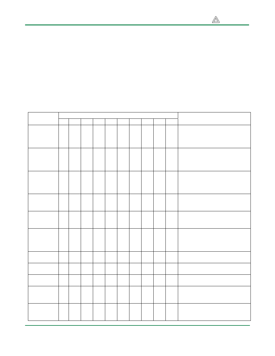
Display Instructions and Instruction Codes
Instruction bit assignments
Instruction
RS R/W DB7 DB6 DB5 DB4 DB3 DB2 DB1 DB0
Description
Clear
Display
0 0 0 0 0 0 0 0 0 1
Clear display by writing a 20H to
all DDRAM locations; set
DDRAM address register to 00H;
and return cursor to home.
Return
Home
0 0 0 0 0 0 0 0 1 X
Return cursor to home (upper left
corner), and set DDRAM address
to 0H. DDRAM contents not
changed.
Entry mode
set
0 0 0 0 0 0 0 1 I/D
SH
I/D = ‘1’ for right-moving cursor
and address increment; SH = ‘1’
for display shift (direction set by
I/D bit).
Display
ON/OFF
control
0 0 0 0 0 0 1 D C B
Set display (D), cursor (C), and
blinking cursor (B) on or off.
Cursor or
Display shift
0 0 0 0 0 1 S/C
R/L
X X
SC = ‘0’ to shift cursor right or
left, ‘1’ to shift entire display
right or left (R/L = ‘1’ for right).
Function
Set
0 0 0 0 1 DL
N F X X
Set interface data length (DL =
‘1’ for 8 bit), number of display
lines (N = ‘1’ for 2 lines), display
font (F = ‘0’ for 5x 8 dots)
Set CGRAM
Address
0
0
0
1
AC5 AC4 AC3 AC2 AC1 AC0 Set CGRAM address counter
Set DDRAM
address
0
0
1
AC6 AC5 AC4 AC3 AC2 AC1 AC0 Set DDRAM address counter
Read busy
flag/ address
0 1 BF
AC6
AC5 AC4 AC3 AC2 AC1 AC0
Read busy flag and address
counter
Write data
to RAM
1 0 D7 D6 D5 D4 D3 D2 D1 D0
Write data into DDRAM or
CGRAM, depending on which
address was last set
Read data
from RAM
1 1 D7 D6 D5 D4 D3 D2 D1 D0
Read data from DDRAM or
CGRAM, depending on which
address was last set