Explanation of jacks, Chapter 1 – RCA Flat Panel Television User Manual
Page 18
Attention! The text in this document has been recognized automatically. To view the original document, you can use the "Original mode".
C^iiiiiiectioiiis & Set« P
Explanation of Jacks
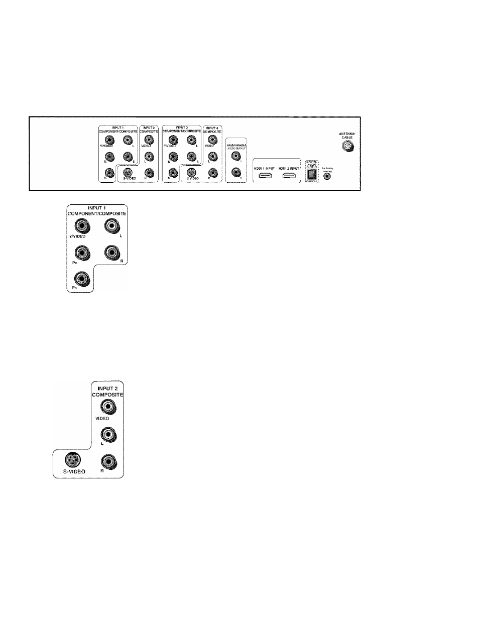
The diagrams laelow illustrate jacks found on the back of the IV. When connecting cables, be
sttre to conirect corresponding outputs airci inputs (video inj^ut into video output, right audio
input itrto light audio output, etc.),
Tip
inputs 1 and 3 can be used as either component
video (YPB PR) inputs or composite video
(Y/Video) inputs.
INPUT 1 and 3 COMPONENT/COMPOSITE INPUTS
Provides connection to an
(analog) video device with either composite or component otitputs stich as a VCR
or DVD jalayer.
•
R
Audio
provides right audio connection and connector is usually red.
•
L Audio
provides left audio connection and connector is usually white,
•
Y/Vid,eo
Pp Pjj Unlike a single video input, compctnent (Y Pg Pj,,) video
maintains the video signal as three separate pans through these three jacks.
To ensure maximum picture tiuality, use three video cables or component
video cables for the Y Pg P^, connections. Accepts 480i, 480p, 720p, and fOSOi
signals, .if you’re connecting to a device with a Video jack instead, you can
still u.se the Y'Video jack.
Note:
Also, reniemher to connect the left and right audio cables because the
Y, Ph, Pr cables carry only the picture signal, not the sou nd,
INPUT 3 COMPONENT/COMPOSITE INPUT
Provides connection to an
* •
additional optional video device, such as a DVD player or satellite receiver. The
jacks are the same as described above for INPUI' 1.
INPUT
2
and
4
COMPOSITE INPUTS
Connect an N1VC (analog) device, I’hese
jacks are tised for most audio/video connections between devices. The audio/
video jac:ks are often color coded (yellow for video, red for right audio, and white
for left audio).
•
R
Audio
provides right atidio connection and connector is tisiiaily red.
•
L Audio
provides left
audio connection and connector
is usually
white.
• V (Video)
prov ides composite video t:onnection and connector is u.sually
yellow.
•
S-VIDEO
Lets you c:onnect an S-Video cable for better picture quality to a
device with S-Video capability, sudi as a VCR or DVD player. The S-Video
jack provides better picture equality than the comjvosite video jacks becatise
tlie c:olor part of tlie signal i.s .separated from the black and white part of the
picture.
When using S-Video, make sure to connect the two audio caitles as well as
tlie S-Video connector.
INPUT
4
COMPOSITE INPUT
Provides connetlion to an additional optional
video device, such as a DVD player or satellite receiver. The jacks are the same as
described above for INPLU’ 2.
18
Chapter 1