Carl Goldberg GBGA0067 User Manual
Page 32
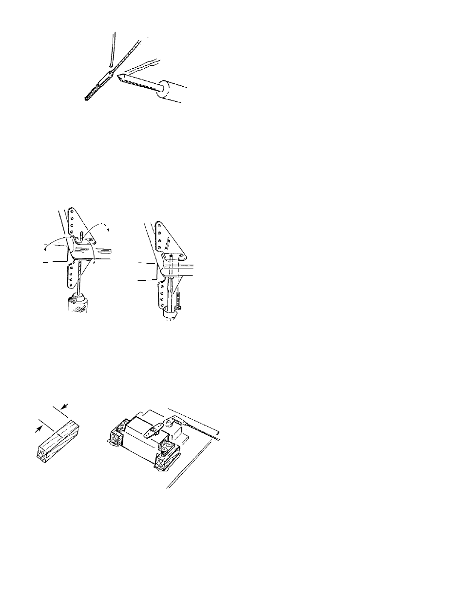
2. Solder a threaded coupler to one end of each
cable.
Lay the cable over the plan and cut to length.
Solder a threaded coupler to the cut end of
each cable.
3. Glue the hooded exits to the fuselage and
thread the cable assemblies from the rudder
servo opening to the control horns.
4. Install a CONTROL HORN on each side of the
rudder, directly opposite from one another.
Drill two 1/16” holes into one of the horn and
thread the two 2-56 screws into the horn.
5
Thread the SNAP LINKS onto the threaded
couplers and attach the links onto the rudder
control horns.
5. Cut the remaining 3/8 sq. piece of bass from
the elevtor pushrod into a 2” length. Then, cut
this piece into two equal pieces.
Glue the two small blocks to the servo tray to
raise the rudder servo, as shown on the plan.
Mount the servo (a ball-bearing servo is rec-
ommended) and, with the servo in the neutral
position, attach and adjust the cables until the
rudder is centered.
NOTE: Cables need only be tight enough to eliminate
slack.
32
RUDDER SERVO
SERVO TRAY
2-56 x 3/4"
SCREW
1/16" DRILL
SOLDER
1"