Carl Goldberg GBGA0067 User Manual
Page 24
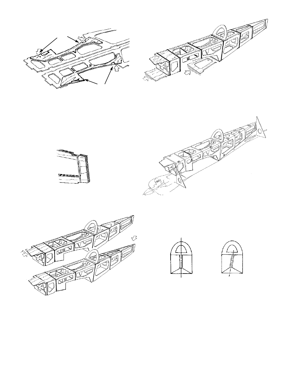
7. Positon, but DO NOT GLUE, FORMERS A, B,
B2, C, F, G, and H. Use a rubber band at each
former location to hold the fuselage together.
8. Slide the TOP FRONT (note slant) and the
TOP AFT under the rubber bands and into the
alignment notches. DO NOT GLUE.
9. Invert the fuse and slide the BOTTOM AFT and
the LANDING GEAR COVER PLATE into the
notches provided. Again, DO NOT GLUE.
10. Position the fuselage assembly over the bottom
view of the plan and check the alignment.
Secure the assembly with small pieces of mask-
ing tape, as shown.
Sight check along the fuselage to ensure that
the fuse is straight, not twisted.
5. Lay the FUSELAGE SIDES on a flat surface
side-by-side, in a mirror-image configuration.
This will ensure that you build a left and a right
fuselage side.
Aligning the front and rear points for correct
positioning, glue a WING SADDLE DOUBLER
to each fuse side.
6. With the doublers face-to-face, rubber band
the fuse sides together at the rudderpost loca-
tion.
24
ALIGN
ALIGN
TAPE IN PLACE
PLAN
LIKE THIS
NOT LIKE THIS
SLANT