Carl Goldberg GBGA0067 User Manual
Page 25
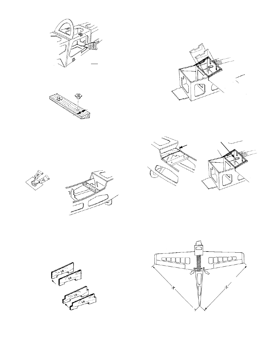
11. When the fuselage is perfectly aligned, glue all
of the areas where the sides, top, bottom, and
formers join.
12. Insert the remaining 6-32 blind nuts into the pre-
drilled holes in the WING MOUNTING BLOCK.
NOTE: Make sure the blind nuts are inserted into the
side of the mounting block where the holes are
centered.
Tap with a hammer to ensure the spurs are fully
set into the wood.
13. With the blind nuts on the inside the fuse, place
the mounting block into the cut-outs in the wing
saddle doubler and the fuselage sides. Trim, if
necessary, to achieve a good fit. Then, using
epoxy, glue in place.
NOTE: THIS IS A HIGH STRESS AREA. THE BET-
TER THE MOUNTING BLOCK FITS INTO THE
SOCKET, THE STRONGER THE JOINT WILL BE.
14. Form four 2-ply assemblies from the four LAND-
ING GEAR DOUBLERS.
When the laminated assembles are dry, test fit
in position. The assemblies with the tabs fit at
the slotted locations between Former B and
Former B2. The assemblies without the tabs
go along the fuse sides.
Epoxy securely in place.
15. Epoxy the 1/4 x 2-1/4 x 5-11/16” ply landing gear
plate between the fuse sides and into landing
gear doublers.
Now get the wing, which will be needed for the next
few steps.
16. Place the fuselage, bottom up, on a flat surface.
Glue the WIND STOP to the fuse sides and the
doublers.
Insert the wing dowel through the slightly over-
sized hole in Former B2. Slide the wing as far
forward as it will go. Make sure that the wing fits
tightly all along the wing saddle.
17. True the wing to the fuselage by adjusting the
distance from the wing-tip to the tail until both
dimensions are equal. Mark the wing for refer-
ence and tape in place.
25
HOLE IS CENTERED
TABBED DOUBLERS
UNTABBED DOUBLERS
MARK WITH TAPE
WIND STOP
L.G. PLATE
GLUE ALL SEAMS
WING DOWEL