Carl Goldberg GBGA0067 User Manual
Page 31
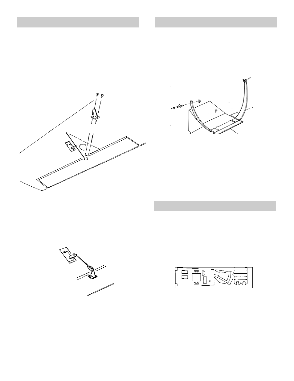
AILERON SERVO CONNECTION
LANDING GEAR INSTALLATION
RUDDER CABLE INSTALLATION
1. Collect the following items:
(4) #2 x 5/16" SHT. METAL SCREWS PT.#1086
(2) .078 x 10" THREADED ROD
PT.#1272
(2) SNAP LINKS
PT.#1405
(2) LONG CONTROL HORNS
PT.#1407
(2) SERVOS
NOT INCLUDED
(2) 18" SERVO EXTENSIONS NOT INCLUDED
2. Install the aileron servos, if you have not
alreeady done so.
3. Lay the triangle along the hinge line and over
the last hole on the servo arm to locate the
control horn.
Attach the control horns by screwing two #2 x
3/8” screws into the plywood back-up inside
the ailerons.
4. With the ailerons and the servos in the neutral
position, connect the pushrods.
1. Collect the following items:
(1) FORMED ALUMINUM GEAR
PT.# 1367
(2) THREADED AXLE
PT.# 1369
(4) #6 x 3/4” SHT. METAL SCREW
PT. #1082
(4) #6 WASHER
PT. #1140
(2) 3-1/2" WHEEL
(NOT INCLUDED)
(4) C.G.P 3/16" WHEEL COLLAR (NOT INCLUDED)
2. Mark the centerpoint of the landing gear cover
plate and the formed LANDING GEAR, making
sure they are aligned.
3. Using four #6 x 3/4” sheet metal screws, per-
manently mount the landing gear through the
cover plate into the 1/4” ply landing gear
mount.
4. Bolt the AXLES to the landing gear and install
the wheels.
NOTE
The SUKHOI uses a pull-pull system. Therefore, the
rudder servo must be located as shown on the plan to
ensure the correct cable alignment with the cable exits.
This feature was designed into the fixtured placement
of the servo tray supplied in this kit. If you decide not
to use the tray, make sure that you place the servo as
shown on the plan.
1. Collect the following items:
(1) D/C SHT. 6712 PLY
PT. #3671
CONTAINS RADIO TRAY
(2) .030 x 34" CABLES
PT.#1289
(4) THREADED COUPLERS
PT.#1192
(2) LONG CONTROL HORNS
PT.#1407
(2) 2-56 x 3/4" PAN HEAD SCREWS
PT.#1042
(4) SNAP LINKS
PT.#1405
(2) HOODED P.R. EXITS
PT.#1453
(1) 3/8" SQ. x 2" BASS
CUT FROM PT.#3674
31
#2 x 5/16" SCREW
ALIGN WITH HOLE IN
SERVO ARM
"Z"BEND
.078 WIRE
#6 x 3/4" SCREW