Carl Goldberg GBGA0059 User Manual
Page 28
28
9. Wrap the radio receiver carefully in foam rub-
ber, making sure the antenna wires extend out-
side the foam. Do not cut the antenna wires.
Place the receiver just to the rear of the battery
pack.
Drill a small hole in the bulkhead and thread the
antenna further back, under the wing rest rails
and through the fuse.
Drill a small exit hole in either side of the of the
fuse, just before the rear former, and thread the
antenna out through it.
Lead the antenna to the top of the fin and
scotch tape in place.
10. Referring to the plan and the radio installation
diagram at the beginning of this secion, mark
the side of the fuse for the switch location.
Cut a hole in the fuse side, making sure it is
long enough to permit the switch button to
move freely to both the “On” and “Off” posi-
tions.
After determining which is the “On” position,
mount the switch with the “On” setting forward.
Install with the switch screws.
On the outside of the fuselage, clearly mark
which is the “On” and the “Off” setting with the
decals provided in this kit.
11. Mount the charging jack in the fuse side, using
the same method as was used with the switch.
12. Gather all excess wires and cables together
behind the receiver and store by holding down
with foam.
13. Switch on the radio system and set the control
surfaces as follows.
With the elevator trim tab on the transmitter set
in the center position, adjust the elevator mini-
snap until the top of the elevator is flat with the
top of the stab.
With the rudder trim tab set in the center posi-
tion, adjust the rudder mini-snap until the rud-
der points dead straight ahead.
BALANCING THE AIRCRAFT
IMPORTANT: NEVER NEGLECT THIS STEP WITH
ANY AIRPLANE. If you try to fly a plane with the bal-
ance point behind the recommended range, you run
the risk of having an unstable aircraft and the strong
likelihood of a crash. TAKE THE TIME TO PROPER-
LY BALANCE YOUR MODEL!
10-1/2”
6”
3”
3”
1. Refering to the plan, locate a point about 1/3 of
the way back from the leading edge of the
wing. This is the center of gravity (C.G.). When
all equipment is installed, your model must bal-
ance at this point.
DO NOT ATTEMPT TO FLY YOUR AIRCRAFT UNTIL
YOU HAVE BALANCED IT CORRECTLY.
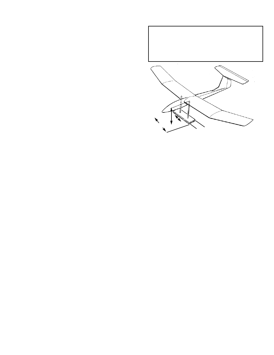
Although it is possible to balance a model by
perching it on the thumb and forefinger of your
left hand while steadying it with your right
hand, a much better way to to set us a balanc-
ing stand as shown above.
2. Use two 1/4” dowels with rounded tops, spaced
far enough apart to clear the fuselage. Mark
the C.G. on the underside of the wing and set
the model on the dowels at that location.
3. Referring to the plan, slide the 1/16” ballast
bulkhead (former) forward until it is snug and
glue in place.
Add lead weight in the nose area shown until
the fuselage is parallel to the base of the bal-
ancing fixture.
Mix some epoxy and pour it over the lead.
When hardened, it will secure the ballast per-
manently.