Carl Goldberg GBGA0059 User Manual
Page 25
25
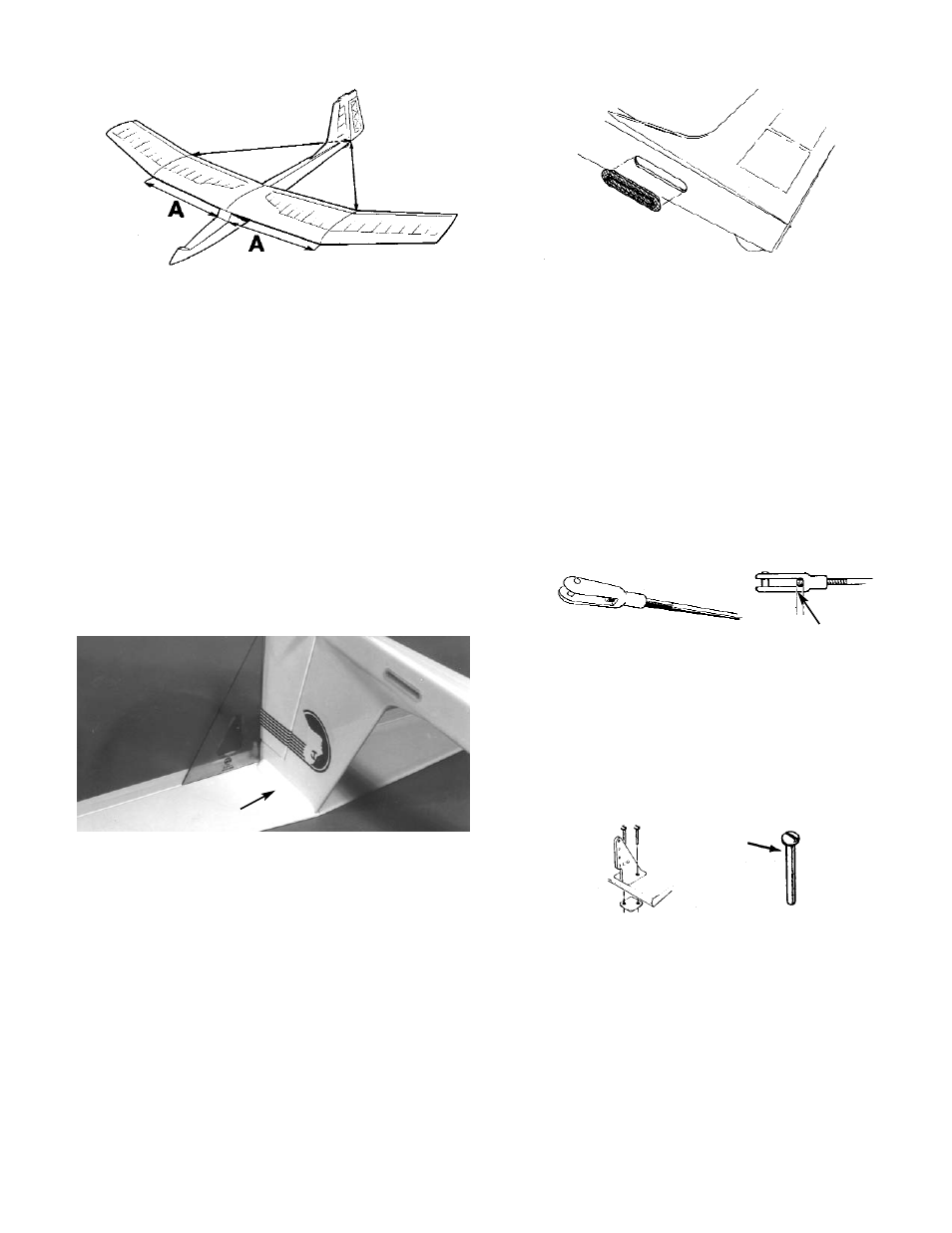
1. Cut the covering at the pushrod exit location on
the left side of the fuse. Install the nylon
pushrod exit guide and glue in place.
2. Referring to the plan, mark the location of the
rudder control horn.
Without attaching the snap links, Insert the
pushrod into the fuse at the wing rest area and
going back to the rudder. Make sure the thread-
ed rod heads straight to the control horn loca-
tion. If it does not, make any necessary adjust-
ments.
Move the pushrod back and forth to simulate
the servo action. Remove the pushrod for
adjustment, if necessary, to achieve a smooth
operation.
TO OPEN, INSERT BLADE OF SCREW
DRIVER AND TWIST.
ALLOW ABOUT
1/8" OF THREAD
TO PROUDE
3. When satisfied with the installation of the
pushrod, install the mini-snap link onto the
threaded end of the pushrod. Use a screw driv-
er blade to open the link. Holding the pushrod
wire with a pliers, twist a mini-snap onto the
threaded rod, so that the rod can be seen in the
center of the snap link.
4. Again referring to the previously marked control
horn location, install the control horn on the
rudder.
Adjust the pushrod, as necessary, and connect
the mini-snap to the 2nd closest hole to the
hinge.
INSTALLING PUSHROD
WING/FUSE ALIGNMENT
1. Position wing dowels so that they protrude
equally out of both sides of the fuse and glue in
place.
2. Using #64 rubber bands, mount the wing on the
fuse. Then, measure carefully from the fuse
sides out to the polyhedral breaks (arrows "A"),
making sure that the wing is centered.
Next, measure from the polyhedral breaks to
the back end of the fuse. Mark the wing and
the fuse with matching line-up points (colored
tape or washable marker).
3. Fit the stab onto the top of the fin, making sure
the alignment is square.
Trace the area where the stab meets the fin
and carefully remove the covering on the inside
of the trace lines and on the top of the fin. Do
not cut into the wood and keep 1/8" inside
the trace lines. Then epoxy the stab to the fin.
4. Reinforce the structure by gluing 5/16" triangle
stock under the stab, on each side of the fin.
TRI STOCK
#2-56 x 1/2" SCREWS
NUT PLATE
CONTROL HORN