Removable tip option – Carl Goldberg GBGA0059 User Manual
Page 10
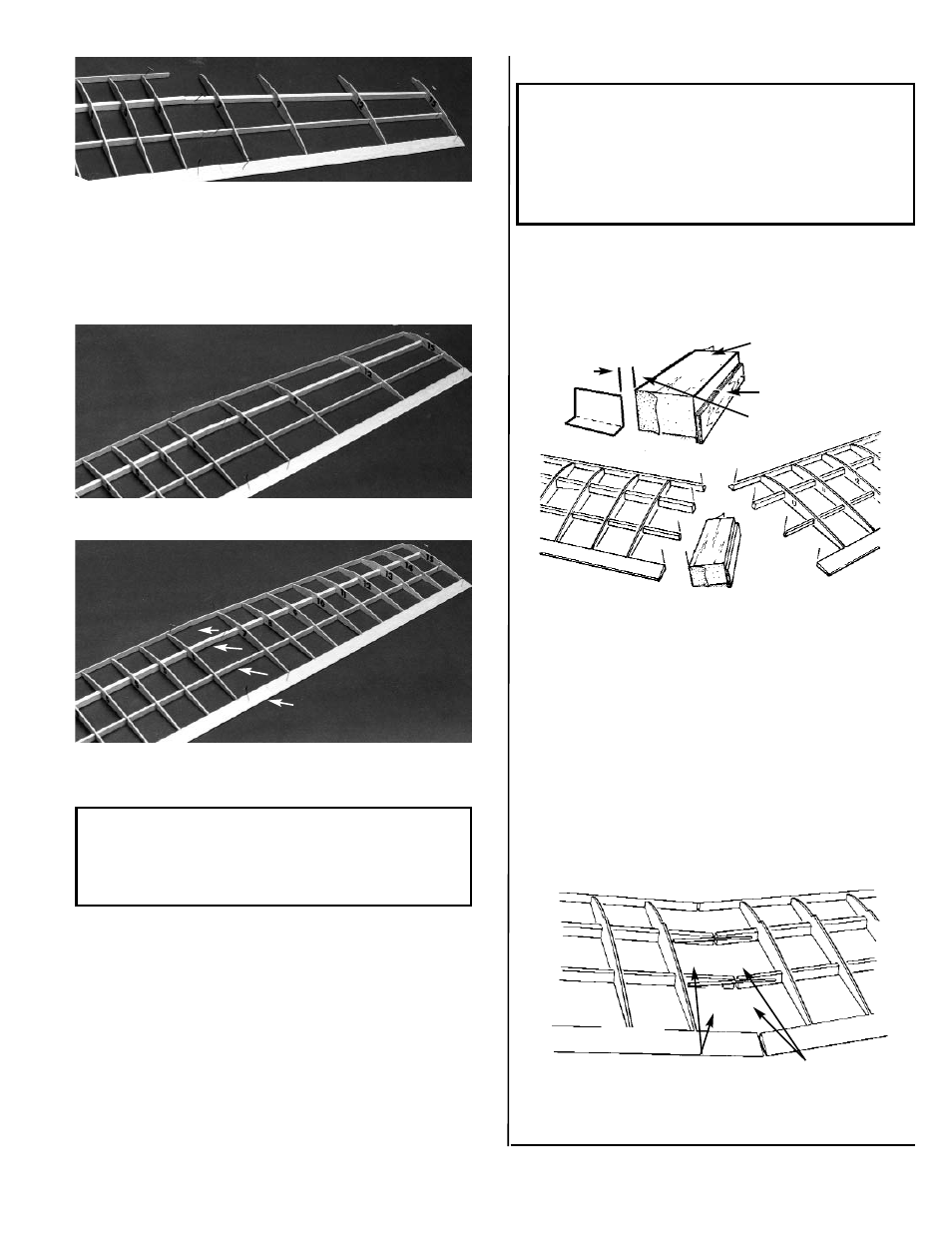
11. Using no glue, set ribs #7, 9,12, and 15 in their
respective T.E. notches, hooking them over the
spars as you go.
Making sure the T.E. and the ribs are correctly
aligned over the plan, pin in place.
Glue the ribs to the spars and the T.E.
12. Pin the outboard L.E. in place and glue it to the
ribs.
13. One at a time, position and then glue the
remaining ribs #8 through #14 in place. Let dry
thoroughly.
NOTE: IF YOU ARE CONSTRUCTING A ONE-
PIECE WING, CONTINUE AT STEP 14. IF YOU
WISH TO BE ABLE TO REMOVE THE WING TIP,
REFER TO THE FOLLOWING OPTIONAL
INSTRUCTIONS.
DO NOT GLUE
IN THIS AREA
10
NOTE: The materials needed to make the wing tip
removable are NOT INCLUDED in your kit.
Necessary templates for this option are found in
the upper right corner of the wing half of the plan.
Follow these steps ONLY IF YOU WANT TO BE
ABLE TO REMOVE THE WING TIPS. Otherwise,
continue at Step 14.
REMOVABLE TIP OPTION
A. Collect the following items:
1/8” x 3” x 18” HARD BALSA SHEET
3/32” x 12” MUSIC WIRE
3/32 I.D. x 6” BRASS TUBE
3/34” VINYL ELECTRICAL TAPE
SANDING
BLOCK
SANDING
ANGLE TEM-
PLATE
POSITION & GLUE
SCRAP PLY TO BACK SO
THAT FRON MATCHES
WITH TEMPLATE.
B. Make a sanding block from 1/8” scrap plywood,
using the SANDING ANGLE TEMPLATE from
the plan. Make sure to establish tthe proper
sanding block angle, as show above.
C. From the 1/8” hard balsa sheet, cut four NEW
#6 ribs. DO NOT USE THE #6 die cut ribs
that are included with your kit.
D. Remove the pins from the inboard panel and
use the sanding block to gently sand the poly-
hedral ends of the spars, the L.E., and the T.E.
to insure uniform vertical surfaces.
E. Referring to Step 14 for correct use of the die-
cut wing gauges, raise the inboard wing panel,
as shown.
3/32” I.D. TUBE
3/32” WIRE
INBOARD PANEL
F. Position the 3/32 x 3” wire on the back of the
spars, as shown.