Carl Goldberg GBGA0059 User Manual
Page 11
Referring to the TIP OPTION on the plan, care-
fully groove the spars for the wire and for the
brass tube.
G. Tack-glue the WIRE to the OUTBOARD SPAR
and the BRASS TUBE to the INBROARD
SPAR.
Plug the wing panels together and make cer-
tain the wing structures butt evenly at the poly-
hedral joint. If adjustments are needed, take
the panels apart and rework the grooves slight-
ly.
When satisfied with the fit of the joint, glue the
metal parts in place.
H. With the wing panels plugged together, posi-
tion the new #6 ribs at the polyhedral joint. The
ribs should be tilted slightly toward the out-
board panel, so that they match the spar angle.
TAKING CARE TO NOT GLUE THE WING
PANELS TOGETHER, carefully glue the ribs to
their respective wing panels.
I.
Unplug the wing panels. Then, working on first
the inboard panel and then the outboard panel,
wrap a about 2” of 3/4” wide nylon fabric
(included in your kit) around each of the spars
to secure the wire and brass tubing.
Saturate the nylon fabric with Super Jet or Jet
Epoxy, to create a sturdy bond.
WRAP NYLON AROUND SPARS,
TUBES, AND WIRES
11
J. Add gussets (D/C Sht. 4006) at the L.E. and
T.E., as shown above.
NOTE: This completes the removable tip option con-
struction for the first wing half. When working on the
second wing half, you again will follow the above
instructions. After the wing parts are covered, the
removable panels are fastened to the inboard wing
sections using vinyl electrical tape. This tape holds
firmly, yet can be removed without damaging the cov-
ering material.
NOW PROCEED DIRECTLY TO STEP 19.
14. With the outboard panel still pinned down, raise
the inboard panel and support it with the wing
dihedral gauges under the first rib #5 location, as
shown on the plan.
IMPORTANT: The end of the gauge stamped “A” must
be up. Hold the gauges firmly in place by tack-cement-
ing, clothespins, etc.
Carefully inspect the panel joint to make sure all
of the end pieces of the inboard panel fit tightly
to those of the outboard panel. If one part pro-
trudes too much, sand slightly for a better fit.
WARNING: always sand just a little at a time, so
that you do not remove too much wood. You
may find it helpful to use the sanding tool
described in the removable tip option.
15. TEMPORARILY install the diihedral joiners on
each side of the spars. Use die-cut clampls to
hold in place.
When satisfied with the fit of the inboard and out-
board panels, pin in place, as shown above.
16. Remove the dihedral joiners and apply a liberal
bead of Super Jet to all joints of the L.E., spars,
and T.E.
Quickly apply glue to the joiners and immediate-
ly reinstall. Use the clamps again to hold both
joiners tight to the spars. Allow to dry.
IMPORTANT: "A" AT TOP
MATCH GAUGES WITH PLAN
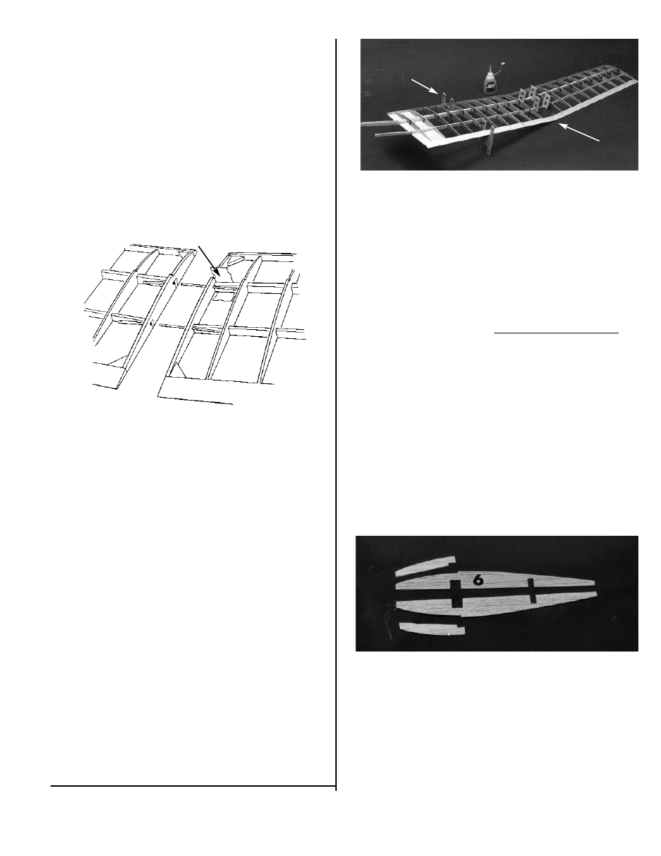
17. Lay out two #6 ribs, and two doublers, as
shown.
Glue rib doubler #6a to each rib, taking care to
make on left and one right rib.
18. Position rib #6 so that it aligns with the joints in
the L.E., the spars, and the T.E. Make sure that
the doubler is facing out, toward the outboard
pannel. When satisfied with the fit, glue in
place.
Referring to the plan for location, glue gussets to
rib #6, the L.E., and the T.E.