Radio installation – Carl Goldberg GBGA0059 User Manual
Page 27
27
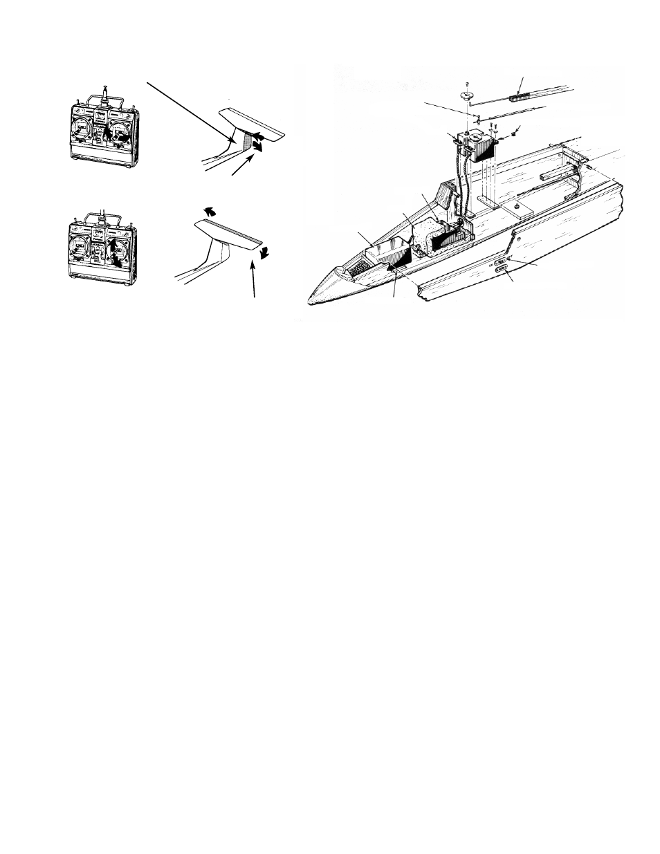
MOVING STICK RIGHT MOVES THE RUDDER RIGHT 1-1/2"
MOVING STICK LEFT MOVES THE RUDDER LEFT 1-1/2"
MOVING STICK FORWARD (AWAY FROM YOU) MOVES ELE-
VATOR DOWN 3/8"
MOVING STICK BACK (TOWARD
YOU) MOVES ELEVATOR UP 3/8"
RADIO INSTALLATION
NOTE: Before installing the radio, read and follow the
instructions included with your radio. Also make sure
the batteries are fully charged and the pushrods are in
place and connected to the control horns. The wires at
the front end of the pushrods should have excess
length, reaching close to former #2.
ASSEMBLE & TEST THE RADIO
BEFORE INSTALLATION
1. Move the control stick from side to side. Apply
tape (on which you can write) to the receiver
plug which goes to the servo that moves. Mark
this wire "RUD." (If your receiver doesn't have
separate plugs coming from it, but does have
places for the servos to plug in, apply the tape
nearby, so that you can mark "R" opposite the
appropriate plug-in location.
2. Move the control stick up and down (away from
you and towards you). Mark the appropriate
plug or plug-in location "ELEV" or "E."
Note that the servo functions are determined by where
they are plugged into the receiver. Be sure to assem-
ble them the same way each time, so that the servos
give you the proper responses.
INSTALLING THE RADIO
1. With the pushrods installed, tape the pushrod-
wires beneath the wing rest strip, so they will be
out of the way.
Insert the soft rubber grommets supplied with
the radio into the mounting holes of the servos.
Measure from the bottom of the servo to the
underside of a grommet and add 3/16" to this
measurement. The total is the height from the
fuse floor to the top of the servo rail.
2. Mark the inner sides of the fuselage at the cor-
rect location for the servo rails.
3. Notch one of the rails so that the cables will
clear the area as they exit from the servo. This
will be the forward rail.
Using either Super Jet or Jet epoxy, glue the
forward rail in place.
4. Placing one servo on the forward rail, deter-
mine the location for the back rail, allowing
approximately 1/16" clearance, so that the
servo can be removed easily.
Glue the rear rail in place.
5. Place both servos in position, with approxi-
mately 1/16" between them, and mark through
the grommets for the location of the servo
mounting screws. Remove the servos.
Using a 1/16" drill bit, drill holes though the rails
for the servo screws.
6. Determine which is the elevator servo and
which is the rudder servo. Locate the rudder
servo on the left and the elevator servo on the
right, as shown on the plans.
Gently fasten the servos to the servo rails with
#2x3/8" sheet metal screws.
7. Untape the pushrod wires from the fuselage
sides and hook them up to the appropriate ser-
vos.
8. Mount the battery pack (which is the heaviest
piece of equipment) as far forward as possible.
Secure it to the floor of the fuse with foam-
backed servo mounting tape, making sure the
final battery position does not interfere with the
canopy fit.
NOTE:YOU MUST ALWAYS USE FRESH DRY
CELLS OR FULLY CHARGED NICADS FOR FLYING.
RUDDER PUSHROD
4-40 x 3/16"
SOCKET HEAD SCREW
SERVO
RUBBER GROMMET
ELEVATOR PUSHROD
ON/OFF SWITCH
RECEIVER
FOAM
BATTERY
CHARGING JACK
FOAM TAPE