Covering & final assembly – Carl Goldberg GBGA0059 User Manual
Page 21
21
COVERING & FINAL ASSEMBLY
ASSEMBLING FIN TO FUSELAGE
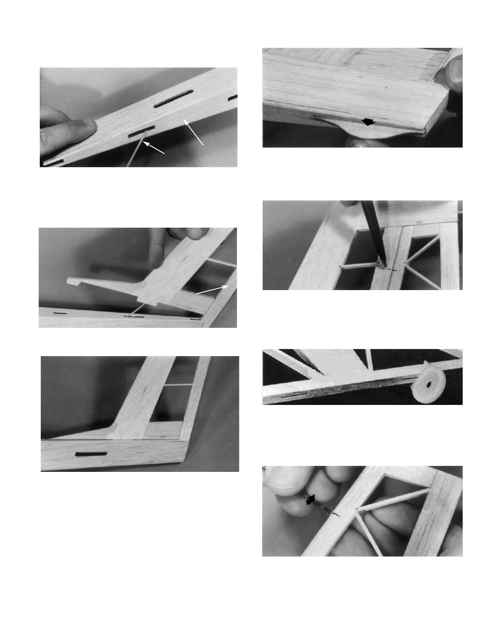
CUTTING HINGE SLOTS
1. Remove the 3/16" balsa spacer from the rear
end of of the fuse.
Insert the nylon guide tube attached to the fin
into the middle slot on the rear top of the fuse,
and guide it completely through the fuse.
FUSE TOP
NYLON TUBE
2. Slide the fin down, inserting the rudder post
into the slot at the end of the fuse.
RUDDER POST
3. Tilt assembly forward and snap the two fin tabs
into the remaining slot.
If satisfied with the fit, apply glue to tabs and
the top of the fuse and glue the fin in place.
Lay the fuse over the plan and check for cor-
rect alignment between the wing rest and the
top of the fin. Trim to match, if necessary.
4. Slide the 1/16" D/C ply tailskid into the slot on
the bottom of the fuse and glue in place.
1. Take the tack-glued stabilizer assembly and
separate the elevator from the stab.
Place the pieces on the plan and mark the
hinge locations onto the stab, the elevator, the
rudder and the fin.
2. Using a CGM centerline marker, mark a center
line along the entire length of the elevator and
the rudder.
Next, mark a centerline at the hinge locations
on the fin and the stab.
3. Using a 1/16" diameter drill bit, bore through at
the hinge marks.